IX. Energy Exchange with Moving Blades
A.
Introduction
So far we have only looked at the thermodynamic results of compressors and
turbines (p’s and t’s).
Now we will look in more detail at how the components of a gas turbine engine
produce these effects. You will learn later (in 16.50 for example) that without
heat transfer, it is only possible to change the total enthalpy of a fluid
with an unsteady process (e.g. moving blades). Still we will use many
of the steady flow tools that we have discussed in thermodynamics and propulsion
by considering the steady flow in and out of a component as shown in Figure
8.1.
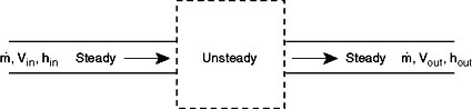
Figure 9.1 Control volume
around compressor or turbine.
B.
The Euler Turbine Equation
The Euler turbine equation relates the power added to or removed from the
flow, to characteristics of a rotating blade row. The equation is based on
the concepts of conservation of angular momentum and conservation
of energy. We will work with the following model of the blade row:
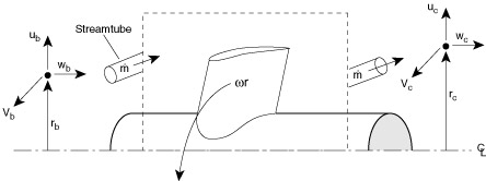
Figure 9.2 Control volume
for Euler Turbine Equation.
Applying conservation of angular momentum, we note that the torque, T,
must be equal to the time rate of change of angular momentum in a streamtube
that flows through the device (In the text: For more information about
angular momentum and rotational energy, see pages 246 and 558 in Hibbler).
Q31 (PDF)

This is true whether the blade row is rotating or not. The sign matters
(i.e. angular momentum is a vector -- positive means it is spinning in one
direction, negative means it is spinning in the other direction). So
depending on how things are defined, there can be positive and negative torques,
and positive and negative angular momentum. In Figure 9.2, torque is positive
when Vtangential out > Vtangential in ----
the same sense as the angular velocity.
If the blade row is moving, then work is done on/by the fluid. The work per unit time, or power, P, is the torque multiplied
by the angular velocity, w

If torque and angular velocity are of like sign, work is being done on the
fluid (a compressor). If torque and angular velocity are of opposite
sign work is being extracted from the fluid (a turbine). Here is another
approach to the same idea:
C.
Multistage Axial Compressors
An axial compressor is typically made up of many alternating rows of rotating
and stationary blades called rotors and stators, respectively, as shown in
Figures 9.3 and 9.4. The first stationary row (which comes in front of the
rotor) is typically called the inlet guide vanes or IGV Each successive rotor-stator
pair is called a compressor stage. Hence compressors with many blade rows
are termed multistage compressors.
Figure 9.3 A typical
multistage axial flow compressor. Copyright Rolls-Royce plc. Reproduced with
the kind permission of Rolls-Royce plc.
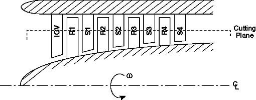
Figure 9.4 Schematic representation
of an axial flow compressor.
One way to understand the workings of a compressor is to consider energy
exchanges. We can get an approximate picture of this using the Bernoulli
Equation, where PT is the stagnation pressure, a measure of the
total energy carried in the flow, p is the static pressure a measure of the
internal energy, and the velocity terms are a measure of the kinetic energy
associated with each component of velocity (u is radial, v is tangential,
w is axial).

The rotor adds swirl to the flow, thus increasing the total energy carried
in the flow by increasing the angular momentum (adding to the kinetic energy
associated with the tangential or swirl velocity, 1/2rv2).
The stator removes swirl from the flow, but it is not a moving blade row
and thus cannot add any net energy to the flow. Rather, the stator rather
converts the kinetic energy associated with swirl to internal energy (raising
the static pressure of the flow). Thus typical velocity and pressure profiles
through a multistage axial compressor look like those shown in Figure 9.5.
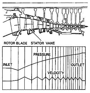
Figure 9.5 Pressure
and velocity profiles through a multi-stage axial compressor. Copyright Rolls-Royce
plc. Reproduced with the kind permission of Rolls-Royce plc.
Note that the IGV also adds no energy to the flow. It is designed to add
swirl in the direction of rotor motion to lower the Mach number of the flow
relative to the rotor blades, and thus improve the aerodynamic performance
of the rotor.
D. Velocity
Triangles for an Axial Compressor Stage
Velocity triangles are typically used to relate the flow properties and blade
design parameters in the relative frame (rotating with the moving blades),
to the properties in the stationary or absolute frame.
We begin by “unwrapping” the compressor. That is, we take a cutting plane
at a particular radius (e.g. as shown in Figure 9.3) and unwrap it azimuthally
to arrive at the diagrams shown in Figure 9.6. Here we have assumed that
the area of the annulus through which the flow passes is nearly constant and
the density changes are small so that the axial velocity is approximately
constant.
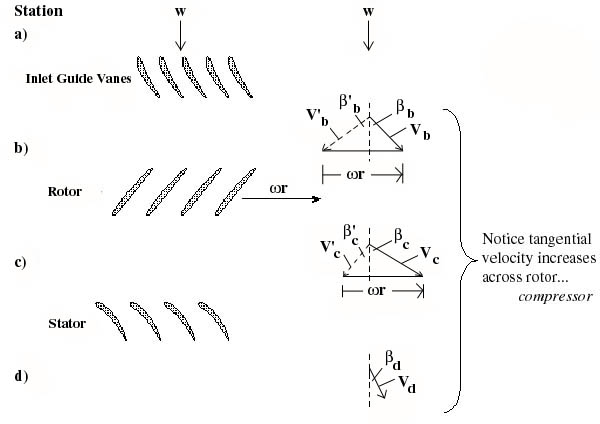
Figure 9.6 Velocity triangles
for an axial compressor stage. Primed quantities are in the relative frame,
unprimed quantities are in the absolute frame.
In drawing these velocity diagrams it is important
to note that the flow typically leaves the trailing edges of the blades at
approximately the trailing edge angle in the coordinate frame attached to
the blade (i.e. relative frame for the rotor, absolute frame for the stator).
Q25 (PDF)
Q30 (PDF)
Interactive program for calculating velocity triangles (by Rodin
Lyasoff)- GO!
[There may be a delay while Java loads.]
|
We will now write the Euler Turbine Equation in terms of stage design parameters:
w, the rotational speed, and bb
and bc’ the leaving angles
of the blades.

From geometry,
vb = wb tan bb
and vc = wc tan
bc = wrc - wc tan
so

or

So we see that the total or stagnation temperature rise across the stage
increases with the tip Mach number squared, and for fixed positive blade angles,
decreases with increasing mass flow. This behavior is represented schematically
in Figure 9.7.
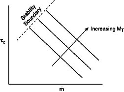
Figure 9.7 Compressor behavior
Homework P8 (PDF)
E.
Velocity Triangles for an Axial Flow Turbine Stage
We can apply the same analysis techniques to a turbine. Again, the stator
does no work. It adds swirl to the flow, converting internal energy into
kinetic energy. The turbine rotor then extracts work from the flow by removing
the kinetic energy associated with the swirl velocity.
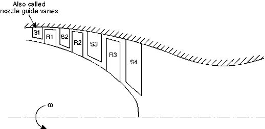
Figure 9.8 Schematic of an
axial flow turbine.
The appropriate velocity triangles are shown in Figure 9.9, where again the
axial velocity was assumed to be constant for purposes of illustration.
As we did for the compressor, we can write the Euler Turbine Equation in
terms of useful design variables:

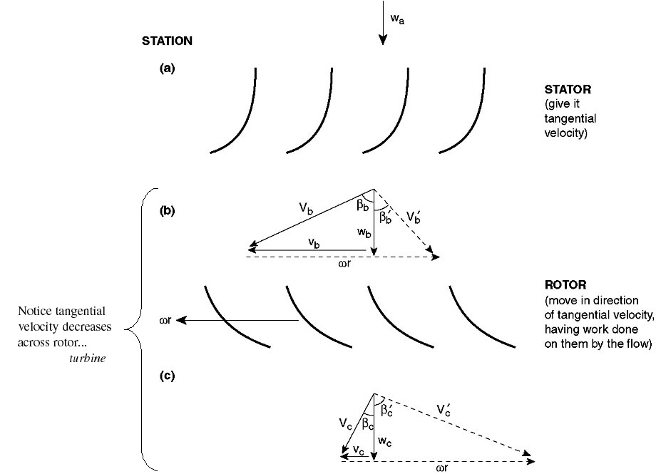
Figure 9.9 Velocity triangles
for an axial flow turbine stage.
Homework P9 (PDF)