-
Frequently (especially for flow processes) it is most useful to express the First Law as a statement about rates of heat and work, for a control volume.
-
Conservation of mass (VW, S & B: 6.1)
-
Conservation of Energy (First Law) (VW, S & B: 6.2)
-
For steady-state (VW, S & B: 6.3)
- Stagnation Temperature and Stagnation Enthalpy
-
The quantity that is conserved is called the stagnation temperature.
-
It is also convenient to define the stagnation enthalpy, hT
-
Note that for a quasi-static adiabatic process
- Example Applications of the Steady Flow Energy Equation (VW, S & B: 6.4)
-
Flow through a rocket nozzle
-
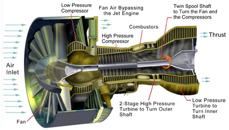
Power to drive a gas turbine compressor
Recall, dE = dQ-dW
For the control volume,
where
![]() rate
of energy transfer to the system as heat
rate
of energy transfer to the system as heat
![]() rate
of work done by the system
rate
of work done by the system
![]()
so
![]() (units
J/s)
(units
J/s)
or
![]()
Neglecting potential and chemical energy (PE and CE)
![]()
Where c is the speed of the fluid, and c2/2 is the kinetic energy of the fluid per unit mass relative to some coordinate system.
If we divide through by the mass flow and set the inlet of the control volume as station 1, and the outlet as station 2, then
![]()
Q6.1 (PDF)
It is also more convenient to divide the work into two terms: 1) the flow work done by the system which is p2v2-p1v1, and 2) any additional work which we will term external work or shaft work, ws. Then we have
![]()
or
![]()
We will call this the steady flow energy equation.
Q6.2 (PDF)
Enthalpy is most useful for separating flow work from external work (as might be produced by a shaft crossing the control volume boundary for instance). In the figure shown below. Heat is added, a compressor is doing work on the system, the flow entering the system does work on the system (work = -p1V1), and work is done by the system through pushing out the flow (work = +p2V2). The first law relates the change in energy between states 1 and 2 to the difference between the heat added and the work done by the system. Frequently, however, we are interested only in the work that crosses the system boundary, not the volumetric or flow work. In this case it is most convenient to work with enthalpy.
This also leads to a direct physical interpretation for enthalpy. In an open flow system, enthalpy is the amount of energy that is transferred across a system boundary by a moving flow. This energy is composed of two parts: the internal energy of the fluid (u) and the flow work (pv) associated with pushing the mass of fluid across the system boundary.
Note that both of the following cases are also frequently encountered. Heat addition, with no external work only flow work:
No heat addition, with external work and flow work:
Q6.3 (PDF) Q6.4 (PDF) Q6.7 (PDF) Q6.9 (PDF)
Homework 8 (PDF)
Homework 9 (PDF)
Suppose that our steady flow control volume is a set of streamlines describing the flow up to the nose of a blunt object.
The streamlines are stationary in space, so there is no external work done on the fluid as it flows. If there is also no heat transferred to the flow (adiabatic), then the steady flow energy equation becomes
![]()
![]()
![]()
The stagnation temperature is the temperature that the fluid would reach if it were brought to zero speed by a steady, adiabatic process with no external work. Note that for any steady, adiabatic flow with no external work, the stagnation temperature is constant.
(The Mach number, M, is the ratio of the flow speed, c, to the speed of sound, a. You will learn more about these quantities in fluids, but it is interesting to see that M2 measures the ratio of the kinetic energy of the gas to its thermal energy.)
![]()
So we can write the Steady Flow Energy Equation in a convenient form as
![]()
 so
we can write
so
we can write 
and define the relationship between stagnation pressure and static pressure as
![]()
where, the stagnation pressure is the pressure that the fluid would reach if it were brought to zero speed, via a steady, adiabatic, quasi-static process with no external work.
Homework 10 (PDF)
An area of common confusion is the frame dependence of stagnation quantities.
The stagnation temperature and stagnation pressure are the conditions the fluid would reach if it were brought to zero speed relative to some reference frame, via a steady, adiabatic process with no external work (add quasi-static for stagnation pressure).
What if the body or reference frame is moving? We know from looking at re-entry vehicles, that the skin temperature is much hotter than the atmospheric temperature. If the atmosphere is assumed still, and we stagnate a fluid particle on the nose of a high speed vehicle (carrying it along with the vehicle and thus essentially giving it kinetic energy) its stagnation temperature is given by
![]()
where c is the vehicle speed. The temperature the skin reaches (to first approximation) is the stagnation temperature. The atmospheric temperature, T, is not frame dependent.
The confusion comes about because T is usually referred to as the static temperature and in common language this has a similar meaning as "stagnation". In fluid mechanics and thermodynamics static is commonly used to label the thermodynamic properties of the gas p, T, etc.–these are not frame dependent. Stagnation quantities are those the flow would arrive at if brought to zero speed relative to some reference frame, via a steady, adiabatic process with no external work (add quasi-static for stagnation pressure). Stagnation quantities depend on the frame of reference.
Thus for a re-entry vehicle, the stagnation temperature (vehicle frame) is hotter than the atmospheric (static) temperature. And in a still atmosphere, the static temperature is the same as the stagnation temperature (atmospheric frame).
For the case shown below, a jet engine is sitting motionless on the ground prior to take-off. Air is entrained into the engine by the compressor. The inlet can be assumed to be frictionless and adiabatic.
Considering the state of the gas within the inlet, prior to passage into the compressor, as state (1), and working in the reference frame of the motionless airplane:
a) Is TT1 greater than, less than, or equal to Tatm?
The stagnation temperature of the atmosphere, TTatm, is equal to Tatm since it is moving the same speed as the reference frame (the motionless airplane). The steady flow energy equation tells us that if there is no heat or shaft work (the case for our adiabatic inlet) the stagnation enthalpy (and thus stagnation temperature for constant Cp) remains unchanged. Thus TT1= TTatm = Tatm
b) Is T1 greater than, less than, or equal to Tatm?
If TT1= Tatm then T1< Tatm since the flow is moving at station 1 and therefore some of the total energy is composed of kinetic energy (at the expense of internal energy, thus lowering T1)
c) Is pT1 greater than, less than, or equal to patm?
Equal, by the same argument as a).
d) Is p1 greater than, less than, or equal to patm?
Less than, by the same argument as b).
Homework 11 (PDF)
A liquid bi-propellant rocket consists of a thrust chamber and nozzle and some means for forcing the liquid propellants into the chamber were they react, converting chemical energy to thermal energy.
Once the rocket is operating we can assume that all of the flow processes are steady, so it is appropriate to use the steady flow energy equation. Also, for now we will assume that the gas behaves as an ideal gas, though in general this is a poor approximation. There is no external work, and we assume that the flow is adiabatic.
Then we can write the First Law as
![]() which
becomes
which
becomes ![]()
or
![]()
therefore
![]()
If we assume quasi-static, adiabatic expansion then
 so
so
Where Tc and pc are conditions in the combustion chamber (set by propellants), and pe is the external static pressure.