
| « Previous: student work sample | Next: Return to Assignment 6 description » |
By Yang Yang and three anonymous MIT students
Coordinate system that we used to light the LEDs from the LilyPad.
These Vertical pins were set to LOW: 11, 12, 13, a0(14), a1(15), a2(16), a3(17), a4(18), a5(19), 2, 3.
These Horizontal pins were set to HIGH: 10, 9, 8, 7, 6, 5, 4.
Charlieplex State Drawing Detail
We did not have enough pins on our LilyPad to control each led separately. Using charlieplexing we can have up to n/2*(n/2) leds, where n is the number of pins on our Lilypad.
A grid of conductive fabric was made, positive legs of the LEDs were sewn to horizontal bars, the ground leg was sewn to the vertical strips.
We could then program the power to be sent to each LED, and turn all the others off by making them the opposite charge of the LED we wanted to light up.
The horizontal pins were set to HIGH and the vertical pins set to LOW. Each state had an associated LED, to turn on a particular pin its horizontal bar was called at HIGH and its vertical bar was called at LOW.
Wikipedia has a good reference article on charlieplexing.
Charlieplexing
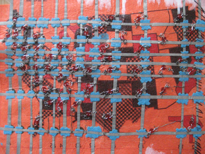
The back of the map. The LEDs are sewn positive leg to horizontal and ground to vertical. Felt pads are used to keep horizontal and vertical layers apart.
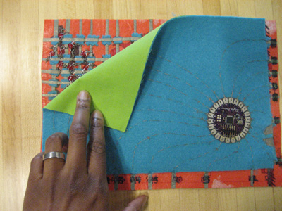
The LilyPad layer set over the charlieplex felt layer. This is the final layer that has the conductive thread connecting from the LilyPad to the charlieplex grid at the edges of the felt.
| « Previous: student work sample | Next: Return to Assignment 6 description » |


