II. Integral Momentum Theorem
We can learn a great deal about the overall behavior of propulsion systems using the integral form of the momentum equation. The equation is the same as that used in fluid mechanics.
We can learn a great deal about the overall behavior of propulsion systems using the integral form of the momentum equation. The equation is the same as that used in fluid mechanics.
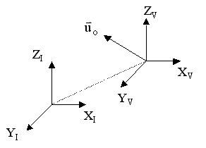 1.
Consider two coordinate systems:
1.
Consider two coordinate systems:a) Inertial (labeled with subscript “I” in diagram at right)b) Fixed to vehicle (labeled with subscript “V” in diagram at right). Moves with velocity
relative to the inertial coordinate system. All velocities relative to the vehicle-fixed coordinate frame are denoted
or
|
|
||||
|
|
|
|
||
| All external forces on control volume (pressure forces, shear forces, body forces) |
Force due to change in inertia for accelerating vehicle
|
Change in momentum of mass in c.v. |
||
To explain the above equation further, consider Figure 2.1
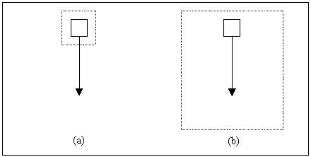
Figure 2.1 Falling blocks.
The falling block labeled (a) has a control volume fixed to it. In this case, the first term on the right hand side of the above equation is nonzero since the control volume is accelerating relative to an inertial reference frame. The second term is zero because the block is not accelerating relative to a coordinate system fixed to the control volume. The opposite is true for the falling block labeled (b), which is falling within a fixed control volume. The first term of the above equation is zero in this case because the control volume is not accelerating relative to an inertial reference frame. The second term is nonzero because the block is moving relative to a coordinate system fixed to the control volume. The mathematical result of both cases is as follows,
(a)
(b)
To continue, the equation can be rewritten as follows,

From conservation of mass,
![]()
so
![]()
NOTE: This is a vector equation.
3. Considering only the components in the x-direction

Then, by the divergence theorem,
![]() where
where ![]() is
outward unit normal vector.
is
outward unit normal vector.

where the forces acting on the control volume may be composed of pressure forces, body forces, and skin friction
Q6 (PDF)
4. For steady flow, with no acceleration of the vehicle then
![]()
This is the form we will use most frequently in this class.
Q8 (PDF)

Figure 2.2 Control volume for application of momentum theorem to a rocket.
![]()
![]()
![]() Static thrust for a rocket engine
Static thrust for a rocket engine
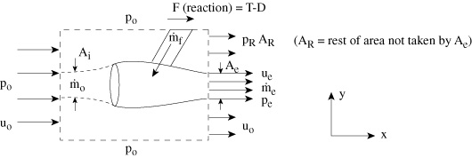
Figure 2.3 Control volume for application of the momentum theorem to a gas turbine engine.

So we have:

Everything that relates to flow through the engine is conventionally called thrust. Everything that relates to the flow on the outside of the engine is conventionally call drag. Therefore, gathering only those terms that relate to the fluid that passes through the engine, we have:
![]()
The thrust is largely composed of the net change in momentum of the air entering and leaving the engine, with a typically small adjustment for the differences in pressure between the inlet and the exit. We could have arrived at the same equation by considering only the streamtube that passes through the engine as shown below:
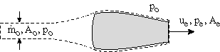
Figure 2.4 Control volume for flow through engine.
Homework P1 (PDF)
Homework P2 (PDF)
Homework P3 (PDF)
| << Previous | Unified Propulsion | Next >> |

