
Lab 1: Disassembly and Assembly of Engines
NOTE: Everybody should wear safety glasses.
The purpose of this session is to get some hands-on experience on the mechanical aspect of the engine. You should learn the mechanical construction of the engine, how the different components are arranged, and get a feel for the size and weight of the components. It is important to know the numbers. Do weigh and measure the components. Since there are a lot of numbers to be measured, divide up the team so that one person is responsible for measurement of a particular component (e.g., the piston). Then the results could be gathered and distributed to everyone.
There are two engines: both are 4-cylinder, 16-valve SI engines for compact vehicles. Both engines have port-fuel injection.
The class will be divided into two groups; each group is responsible to disassemble one engine. However the whole class should participate in the initial ‘looking’ at each of the whole engine and the final study of all the parts for both engines.
Before disassembly, take a look at the engines as a whole, note the arrangement of the different components, the gas exchange circuit: intake, exhaust, EGR (Exhaust Gas Recirculation), and PCV (Positive Crankcase Ventilation) system; the coolant circuit; the fuel flow circuit. Understand the function of these components.
When the engine is opened, look at the valve train arrangement, the lubrication circuit, the EGR route, the coolant passage, and the piston/crank balance weight arrangement.
Record the following in the measurement record form. The measurements may be shared by the group, but the comments and calculations should be done by each individual.
Measure the intake runner length and the size of the manifold (these values do not have to be precise; they are to get you a feel for the typical numbers). Calculate the organ pipe frequency (wave length = 4 x runner length) of the former and the ratio of the latter to the displacement volume.
Measure the bore, the stroke, and the connecting rod lengths.
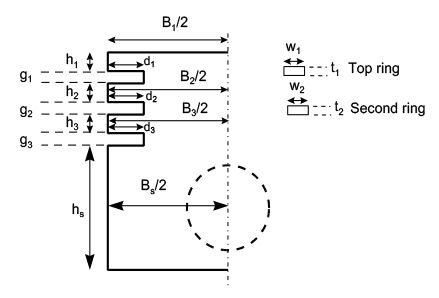
Measure the mass and dimensions of the piston (see figure below). (Why are the values of B1, B2, B3 and Bs different?) Estimate the inertia force required to move the piston at 6000 rpm. Estimate the temperature at which the top land (diameter B1) would be touching the liner which is kept by the coolant to be at 100oC.
Measure the valve diameters and the lifts. (The latter may be obtained from the cam measurements.) Why are the intake and exhaust valve diameters different?
Measure the valve masses. Estimate the spring force required to operate at 1000 and 6000 rpm.
Final measurement record form with comments and calculation results (PDF)
Lab 2: Engine Performance and Emissions Measurements
Engine performance and emissions measurements instruction (PDF)


