
Pre-Lab (PDF)
Lab 1 Description (PDF)
In this lab, the time response of a first-order system is demonstrated. This system consists of a spring and a damper, respectively represented by a cantilever and an air dashpot (Figure 1). The cantilever is made of spring-steel and can be modeled as a linear spring, i.e. the force at the tip of the cantilever is linearly dependent on its displacement. The dashpot can be modeled as a pure damper where the damping force is proportional to velocity as long as the volume of air behind the piston is not too large. The mass of the cantilever can be neglected, as long as the damping of the air dashpot is not too small. Students will observe that the system departs significantly from these idealizations in some circumstances. This nonideal behavior can be the motivation for postulating more complex models.

Figure 1. Idealization: spring and damper. (Image by Prof. Trumper.)
A schematic representation of the system is shown in Figure 2.
Figure 2. Idealization: spring and damper. (Image by Prof. Trumper.)
The glass dashpot is covered with rubber to protect the user if it breaks. In figure 3, the dashpot without the rubber coating is displayed, showing the plunger and the adjustment wheel. This wheel adjusts the damping by changing the opening through which air flows.

Figure 3. Air dashpot without rubber coating. (Image by Prof. Trumper.)
Figure 4 shows a simple ‘webcam’ that records the data as video. The recording software lets you configure the frame rate. By looking at the individual frames of the animation, a table of position and time can be constructed.
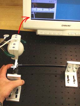
Figure 4. A simple camera records the data as an animation on the screen. (Image by Prof. Trumper.)
The data can then be processed into a plot that can be used to deduce the time constant tau (figure 5).
Figure 5. Response of a first order system to an initial displacement. (Image by Prof. Trumper.)
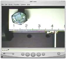
Figure 6. Video Demonstration. (Image by Prof. Trumper.)
Materials and Notes: Practical Info and Comments
-
Airpot Precision Air Dashpot We use an adjustable glass dashpot that is covered with rubber to protect the user if it breaks. Model numbers we use are (2K)S95-A200 or (2K)S160-A200-F275 (603/382-4179). Look at the Web site of Airpot.
-
Angle plates One of the angle plates is a mount for the dashpot, the other a mount and clamp for the spring cantilever. The 3X3X.375 inch angle plates were ordered from Pierce Aluminum. The drawings for these angle plates are: plate 1 and plate 2 (.tif files, use right mouse button and ‘save as…’).
-
Bolts and ruler The bolts should be mounted to serve as stops for the cantilever to prevent damage of the airpot. At first we used plastic rulers as a scale for the deflection of the cantilever, but the plastic rulers appeared to be less visible with the webcam than the pieces of paper.
-
Cantilever spring use flat sheets of spring steel, hole for attachment of damper is hard to machine
-
Optical baseplate OptoSigma, black anodized aluminum, from stock:
- 18x24 inches, 1/4-20 on 1 inch centers: product number 145-1160
- 457x610 mm, M6 on 25 mm centers: product number 145-1165Prices can be found at their Web site. Go to >‘Optical Bases’>‘Baseplates’.
-
Stand Edmund Scientific, clamps for webcam mounting: VWR supply room
-
Webcam Look at Winnov / Solutions for information about these cameras.


