
Pre-Lab (PDF)
Lab 2 Description (PDF)
The dynamics of a spinning shaft and the effects of adding inertia and viscous fluid damping are examined in this lab. Figure 1 shows the actual apparatus.
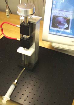
Figure 1. First-order rotary system with damping supplied by cup filled with honey, video image shown on screen. (Image by Prof. Trumper.)
The drawing in figure 2 depicts the most important parts. The shaft and flywheel are modeled as an equivalent rotary inertia.
Figure 2. Drawing of the first-order rotary system. (Image by Prof. Trumper.)
A brass ring can be added to increase the inertia, as shown in figure 3.
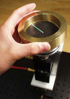
Figure 3. A Brass ring can be added to increase the inertia. (Image by Prof. Trumper.)
The axial position constraint is provided by a ball bearing. This ball bearing is attached to the end of the shaft and rotates on a fixed hardened flat (figure 4). Damping is created by filling with honey the annular space between the end of the shaft and a clear tube. The height of the honey can be changed via the syringe shown in figure 1. The fluid damping can be modeled as an equivalent rotary damper that is linearly proportional to the height L of the viscous fluid.
Figure 4. The end of the shaft is supported by a ball bearing riding on a hardened flat. Honey filling an anular space provides the damping. (Image by Prof. Trumper.)
Figure 5 shows the idealization of this first-order system. We have chosen honey as the viscous fluid to attain time constants on the order of 1 second with relatively loose geometric constraints. Furthermore, honey is environmentally safe and can be cleaned up with water.
Figure 5. Idealization: rotary damping and inertia. (Image by Prof. Trumper.)
Figure 6 shows how the animation is being read from the screen. The data can be read by sticking a transparent angle sheet on the screen.
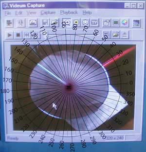
Figure 6. Idealization: rotary damping and inertia. (Image by Prof. Trumper.)
By reading every frame and processing the data (with for example MATLAB®) a plot of the angle versus time can be constructed (figure 7).
Figure 7. Plot of angle vs. time. (Image by Prof. Trumper.)
Clearly, we could automate this data collection by using for example an optical encoder or a tachometer. The reason for using a camera is to make the data acquisition more intuitive for the students in the early labs. To see an example of such a video capture click on the video button:
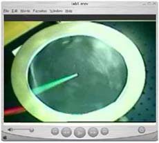
Figure 8: Video Demonstration. (Image by Prof. Trumper.)
Materials and Notes: Practical Info and Comments
- Air bearings New Way®, Each bearing consists of two parts:
(1) S301901 - 3/4" I.D. air bushing
(2) S8019P01 - pillow block housing for the air bushings
Prices for the New Way® bearings can be found at: New Way® Air Bearings. If you are looking for other air bearing types, note that the alignment is a major concern. An advantage of this type of air bearings is that the o-rings allow for some flexibility. Be careful not to damage the o-rings when assembling. Use alcohol as a lubricant when assembling the air bearings. A collar on the shaft is used to disable lifting the shaft to much to avoid honey coming into the bearings. However, it is possible to thoroughly clean the honey out of the bearings with alcohol while they are attached to an air supply. The part of the shaft that goes into the air bearing should be precision ground and unscratched for optimal results. Do not move the shaft inside the bearings when the bearings are not hooked up to air supply to prevent unnecessary scratching of the bearings and shaft. - Air supply Quick connectors and tubing from Beswick
- Angular sheet This is a small version of the polar plot we stick to the screen printed on a transparent sheet. A larger version of this .gif file can be found here. This image can of course be printed with the same dimensions, but with higher resolution.
Small polar plot .gif file. (Image by Prof. Trumper.)
- Collar Whittet Higgins aluminum split-collar clamps: partnumber SC-12A (split collar-size, aluminum). We use 3/4" inner diameter to match the shaft and air bearings. Look at their Web site at Whittet-higgins company go to ‘Collars’>‘SC-A’, order from Kaman Industrial Tech (781/935-7590).
- Flywheel
- Frame
- Honey We have chosen honey as the viscous fluid to attain time constants on the order of 1 second with relatively loose geometric constraints. Furthermore, honey is environmentally safe and can be cleaned up with water. However, honey cristallizes after being exposed to open air for a few days. It is therefore recommended to change the honey when it becomes too thick. Be sure that the honey does not get into the air bearings. For instance use a collar on the shaft to make sure the shaft can not be lifted too far up. If the shaft is not concentric with the look-through tube that holds the honey, the honey will not be distributed evenly across its circumference. This nonideal behavior is hard to model.
- Optical breadboard See Lab 1.
- Shaft, ball bearing and hardened flat Thompson shaft, precision ground 3/4 inch stainless steel; 1/2 inch ball bearing and hardened flat McMaster-Carr
- Stand See Lab 1
- Syringe 20 ml with luer-lok, connection to tubing: luer-lok to tubing Cobert Assoc.
- Webcam See Lab 1


