
Pre-Lab (PDF)
Lab 5 Description (PDF)
First Part
The experience students obtained from the mechanical systems in the previous four labs can be applied to study electrical systems. Systems with masses, springs and dampers have their electrical equivalents with respectively inductors, capacitors and resistors. A major difference between electrical and mechanical systems is that with electrical systems you can achieve nearly ideal behavior far more easily. In this lab, the transfer functions of a few first order electrical systems, shown in figure 1, are measured. The students measure the circuit step response and frequency response functions.
Figure 1. Examples of simple first order electrical circuits. (Image by Prof. Trumper.)
The hardware we need for this lab consists of a signal generator, an oscilloscope and a breadboard to easily put together the electrical components as shown in figure 2.
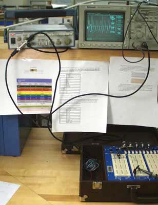
Figure 2. The power amplifier is an Apex PA21 power op-amp in their EK21 evaluation kit. (Image by Prof. Trumper.)
Materials and Notes: Practical Info and Comments
- Electronic kits Electronic School Supplies, kits with electronic components (about $20 each)
Second Part
This lab focuses on second-order electrical circuits, which contain inductors, resistors and capacitors. By measuring the step and frequency responses, the transfer functions can be determined. In figure 1, the idealization of this lab’s circuit is shown.
Figure 1. Idealization of the RLC circuit used in this lab. (Image by Prof. Trumper.)
The input signal of the system is provided by a function generator. Because the function generator and inductor have internal resistances, a more accurate model looks like the circuit in figure 2.
Figure 2. RLC circuit with internal resistances of the function generator and inductor. (Image by Prof. Trumper.)
The internal resistance of the function generator makes the output voltage vg differ from the desired input vi. Therefore an op-amp is used to work as a buffer, as shown in figure 3. Because the input impedance of the op-amp is very high and its output impedance very low, it forces vb to be almost equal to vi as long as the output current does not exceed the limits of the op-amp.
Figure 3. An op-amp buffer forces vb to be nearly equal to vi. (Image by Prof. Trumper.)
The damping ratio can now be adjusted by varying the resistance R1. The resistor be seen as an electrical equivalent of a mechanical damper. Predicted responses of this circuit can be compared with measured ones. Figure 4 shows how magnitude and phase shift can be displayed on an oscilloscope using a sine wave from the function generator. By varying the input frequency, the circuit Bode plot can be generated.
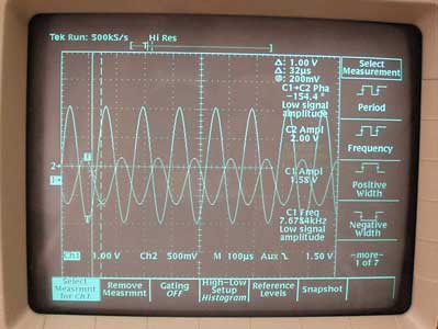
Figure 4. A sine input shows the magnitude and phase shift at a certain frequency. (Image by Prof. Trumper.)


