
To see an animated version of this tutorial, please see the Drawing and Drafting section in MIT’s Engineering Design Instructional Computer System. (EDICS)
Drawing Handout Index
Orthographic or Multiview Drawings
Sections of Objects with Holes, Ribs, etc.
Introduction
One of the best ways to communicate one’s ideas is through some form of picture or drawing. This is especially true for the engineer. The purpose of this guide is to give you the basics of engineering sketching and drawing.
We will treat “sketching” and “drawing” as one. “Sketching” generally means freehand drawing. “Drawing” usually means using drawing instruments, from compasses to computers to bring precision to the drawings.
This is just an introduction. Don’t worry about understanding every detail right now - just get a general feel for the language of graphics.
We hope you like the object in Figure 1, because you’ll be seeing a lot of it. Before we get started on any technical drawings, let’s get a good look at this strange block from several angles.
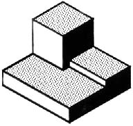
Figure 1 - A Machined Block.
Isometric Drawing
The representation of the object in figure 2 is called an isometric drawing. This is one of a family of three-dimensional views called pictorial drawings. In an isometric drawing, the object’s vertical lines are drawn vertically, and the horizontal lines in the width and depth planes are shown at 30 degrees to the horizontal. When drawn under these guidelines, the lines parallel to these three axes are at their true (scale) lengths. Lines that are not parallel to these axes will not be of their true length.
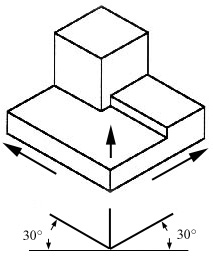
Figure 2 - An Isometric Drawing.
Any engineering drawing should show everything: a complete understanding of the object should be possible from the drawing. If the isometric drawing can show all details and all dimensions on one drawing, it is ideal. One can pack a great deal of information into an isometric drawing. However, if the object in figure 2 had a hole on the back side, it would not be visible using a single isometric drawing. In order to get a more complete view of the object, an orthographic projection may be used.
Orthographic or Multiview Drawing
Imagine that you have an object suspended by transparent threads inside a glass box, as in figure 3.
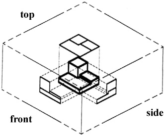
Figure 3 - The block suspended in a glass box.
Then draw the object on each of three faces as seen from that direction. Unfold the box (figure 4) and you have the three views. We call this an “orthographic” or “multiview” drawing.
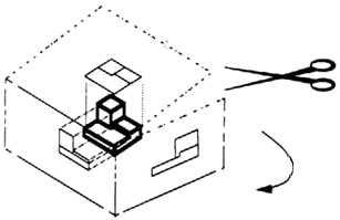
Figure 4 - The creation of an orthographic multiview drawing.
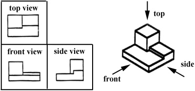
Figure 5 - A multiview drawing and its explanation.
Which views should one choose for a multiview drawing? The views that reveal every detail about the object. Three views are not always necessary; we need only as many views as are required to describe the object fully. For example, some objects need only two views, while others need four. The circular object in figure 6 requires only two views.
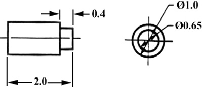
Figure 6 - An object needing only two orthogonal views.
Dimensioning
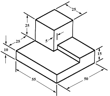
Figure 7 - An isometric view with dimensions.
We have “dimensioned” the object in the isometric drawing in figure 7. As a general guideline to dimensioning, try to think that you would make an object and dimension it in the most useful way. Put in exactly as many dimensions as are necessary for the craftsperson to make it -no more, no less. Do not put in redundant dimensions. Not only will these clutter the drawing, but if “tolerances” or accuracy levels have been included, the redundant dimensions often lead to conflicts when the tolerance allowances can be added in different ways.
Repeatedly measuring from one point to another will lead to inaccuracies. It is often better to measure from one end to various points. This gives the dimensions a reference standard. It is helpful to choose the placement of the dimension in the order in which a machinist would create the part. This convention may take some experience.
Sectioning
There are many times when the interior details of an object cannot be seen from the outside (figure 8).
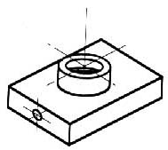
Figure 8 - An isometric drawing that does not show all details.
We can get around this by pretending to cut the object on a plane and showing the “sectional view”. The sectional view is applicable to objects like engine blocks, where the interior details are intricate and would be very difficult to understand through the use of “hidden” lines (hidden lines are, by convention, dotted) on an orthographic or isometric drawing.
Imagine slicing the object in the middle (figure 9):
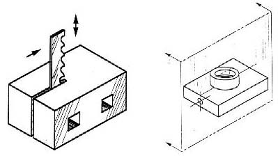
Figure 9 - “Sectioning” an object.
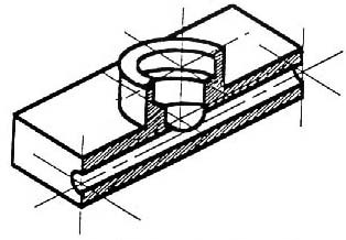
Figure 10 - Sectioning the object in figure 8.
Take away the front half (figure 10) and what you have is a full section view (figure 11).
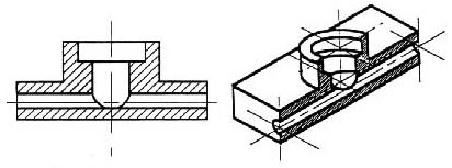
Figure 11 - Sectioned isometric and orthogonal views.
The cross-section looks like figure 11 when it is viewed from straight ahead.
Drawing Tools
To prepare a drawing, one can use manual drafting instruments (figure 12) or computer-aided drafting or design, or CAD. The basic drawing standards and conventions are the same regardless of what design tool you use to make the drawings. In learning drafting, we will approach it from the perspective of manual drafting. If the drawing is made without either instruments or CAD, it is called a freehand sketch.
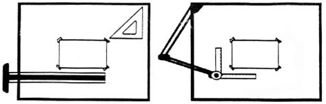
Figure 12 - Drawing Tools.
"Assembly" Drawings
An isometric view of an “assembled” pillow-block bearing system is shown in figure 13. It corresponds closely to what you actually see when viewing the object from a particular angle. We cannot tell what the inside of the part looks like from this view.
We can also show isometric views of the pillow-block being taken apart or “disassembled” (figure 14). This allows you to see the inner components of the bearing system. Isometric drawings can show overall arrangement clearly, but not the details and the dimensions.
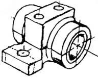
Figure 13 - Pillow-block (Freehand sketch).
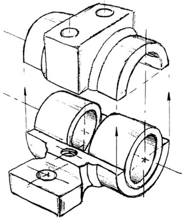
Figure 14 - Disassembled Pillow-block.
Cross-Sectional Views
A cross-sectional view portrays a cut-away portion of the object and is another way to show hidden components in a device.
Imagine a plane that cuts vertically through the center of the pillow block as shown in figure 15. Then imagine removing the material from the front of this plane, as shown in figure 16.
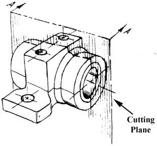
Figure 15 - Pillow Block.
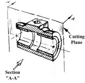
Figure 16 - Pillow Block.
This is how the remaining rear section would look. Diagonal lines (cross-hatches) show regions where materials have been cut by the cutting plane.
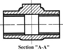
Figure 17 - Section “A-A”.
This cross-sectional view (section A-A, figure 17), one that is orthogonal to the viewing direction, shows the relationships of lengths and diameters better. These drawings are easier to make than isometric drawings. Seasoned engineers can interpret orthogonal drawings without needing an isometric drawing, but this takes a bit of practice.
The top “outside” view of the bearing is shown in figure 18. It is an orthogonal (perpendicular) projection. Notice the direction of the arrows for the “A-A” cutting plane.
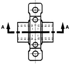
Figure 18 - The top “outside” view of the bearing.
Half-Sections
A half-section is a view of an object showing one-half of the view in section, as in figure 19 and 20.
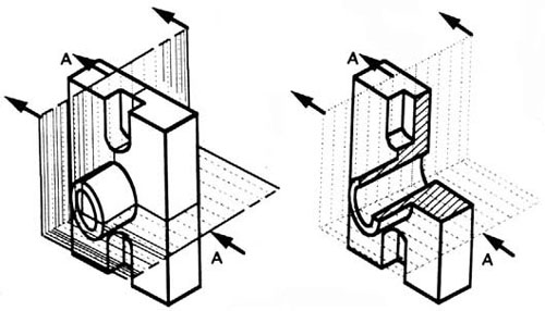
Figure 19 - Full and sectioned isometric views.
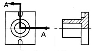
Figure 20 - Front view and half section.
The diagonal lines on the section drawing are used to indicate the area that has been theoretically cut. These lines are called section lining or cross-hatching. The lines are thin and are usually drawn at a 45-degree angle to the major outline of the object. The spacing between lines should be uniform.
A second, rarer, use of cross-hatching is to indicate the material of the object. One form of cross-hatching may be used for cast iron, another for bronze, and so forth. More usually, the type of material is indicated elsewhere on the drawing, making the use of different types of cross-hatching unnecessary.
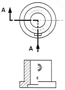
Figure 21 - Half section without hidden lines.
Usually hidden (dotted) lines are not used on the cross-section unless they are needed for dimensioning purposes. Also, some hidden lines on the non-sectioned part of the drawings are not needed (figure 12) since they become redundant information and may clutter the drawing.
Sectioning Objects with Holes, Ribs, Etc.
The cross-section on the right of figure 22 is technically correct. However, the convention in a drawing is to show the view on the left as the preferred method for sectioning this type of object.
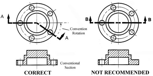
Figure 22 - Cross section.
Dimensioning
The purpose of dimensioning is to provide a clear and complete description of an object. A complete set of dimensions will permit only one interpretation needed to construct the part. Dimensioning should follow these guidelines.
- Accuracy: correct values must be given.
- Clearness: dimensions must be placed in appropriate positions.
- Completeness: nothing must be left out, and nothing duplicated.
- Readability: the appropriate line quality must be used for legibility.
The Basics: Definitions and Dimensions
The dimension line is a thin line, broken in the middle to allow the placement of the dimension value, with arrowheads at each end (figure 23).
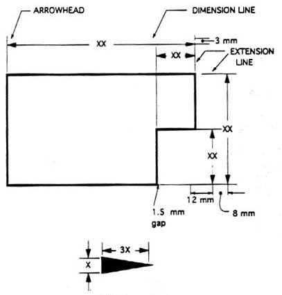
Figure 23 - Dimensioned Drawing.
An arrowhead is approximately 3 mm long and 1 mm wide. That is, the length is roughly three times the width. An extension line extends a line on the object to the dimension line. The first dimension line should be approximately 12 mm (0.6 in) from the object. Extension lines begin 1.5 mm from the object and extend 3 mm from the last dimension line.
A leader is a thin line used to connect a dimension with a particular area (figure 24).
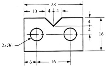
Figure 24 - Example drawing with a leader.
A leader may also be used to indicate a note or comment about a specific area. When there is limited space, a heavy black dot may be substituted for the arrows, as in figure 23. Also in this drawing, two holes are identical, allowing the “2x” notation to be used and the dimension to point to only one of the circles.
Where To Put Dimensions
The dimensions should be placed on the face that describes the feature most clearly. Examples of appropriate and inappropriate placing of dimensions are shown in figure 25.
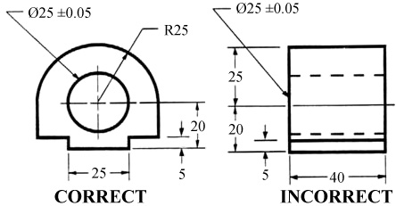
Figure 25 - Example of appropriate and inappropriate dimensioning.
In order to get the feel of what dimensioning is all about, we can start with a simple rectangular block. With this simple object, only three dimensions are needed to describe it completely (figure 26). There is little choice on where to put its dimensions.
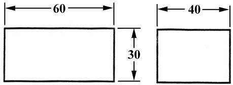
Figure 26 - Simple Object.
We have to make some choices when we dimension a block with a notch or cutout (figure 27). It is usually best to dimension from a common line or surface. This can be called the datum line of surface. This eliminates the addition of measurement or machining inaccuracies that would come from “chain” or “series” dimensioning. Notice how the dimensions originate on the datum surfaces. We chose one datum surface in figure 27, and another in figure 28. As long as we are consistent, it makes no difference. (We are just showing the top view).
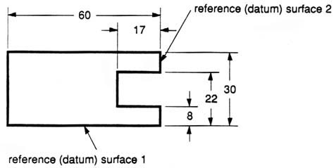
Figure 27 - Surface datum example.
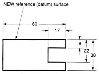
Figure 28 - Surface datum example.
In figure 29 we have shown a hole that we have chosen to dimension on the left side of the object. The Ø stands for “diameter”.
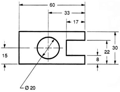
Figure 29 - Exampled of a dimensioned hole.
When the left side of the block is “radiuses” as in figure 30, we break our rule that we should not duplicate dimensions. The total length is known because the radius of the curve on the left side is given. Then, for clarity, we add the overall length of 60 and we note that it is a reference (REF) dimension. This means that it is not really required.
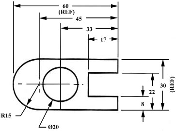
Figure 30 - Example of a directly dimensioned hole.
Somewhere on the paper, usually the bottom, there should be placed information on what measuring system is being used (e.g. inches and millimeters) and also the scale of the drawing.
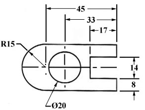
Figure 31 - Example of a directly dimensioned hole.
This drawing is symmetric about the horizontal centerline. Centerlines (chain-dotted) are used for symmetric objects, and also for the center of circles and holes. We can dimension directly to the centerline, as in figure 31. In some cases this method can be clearer than just dimensioning between surfaces.


