2.007 | Spring 2009 | Undergraduate

Design and Manufacturing I

Projects

Your mission: Clean up planet earth and re-establish plant life.

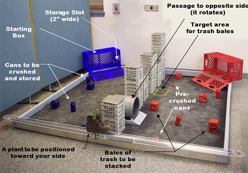
The challenge for this year’s 2.007 robots is to clean up the environment. (Image by Dan Frey.)

Robots begin inside their respective starting box (12" high, 22" wide, 10" deep) with the door closed. Once time starts, the door opens forming a ramp. You will have 60 seconds to exit the box, clean up the table, and/or retrieve the plant. For the first 10 seconds, your robot operates autonomously and in the subsequent 50 seconds under radio control.

The fate of the planet is in your hands!

Table Description

Contest Rules

Parts and Equipment

Project Kit List (PDF)
SolidWorks Parts Archive (ZIP) (This ZIP file contains: 36 .sldprt files, 1 .rpt file, 1 .xlo file, 1 .igs file and 1 .sldasm file.)
Notes on Lithium Polymer Batteries (PDF)

Milestones

WEEK # LAB ACTIVITIES MILESTONES
1 Explore kit & contest (PDF) Kit and contest exploration (PDF)
2 Build a simple car & preliminary strategy (PDF) Develop strategy and work toward final car design (PDF)
3 Design concept (PDF) Develop concept and finalize car design (PDF)
4 Design of most critical module (PDF) Design MCM and build final car (PDF)
5 Fabrication of most critical module (PDF) Fabricate MCM (PDF)
6 Complete MCM fabrication (PDF)
7 Demonstration of most critical module (PDF) Demonstration of MCM (PDF)
8 Integration of design (PDF) Completion plan (PDF)
9 Demonstration of integrated machine (PDF)  
10 Design iteration (PDF)  
11 Fabrication of improved machine (PDF)  
12 Demonstration of improved machine  
13 Final refinements  
14 Debriefs with section (PDF)  

Past Projects

The 2.007 theme changes every year to provide an ongoing challenge for students and robots.

2003 Project: The Two Tables

2005 Project: Tic Tech Toe

All images courtesy of Alex Slocum.

How To Score

Each contestant’s score is found using the following algorithm:

Score = Scoring Multiplier * [Scoring Bin Total + Marked Side - Penalties]

  1. Scoring Bin Total - The sum of the total points scored by placing colored foam blocks into the various scoring bins. The points are assigned to the contestant by color (e.g. red player gets points for any red block placed in a bin). The point distribution is as shown in the figure.

Scoring Total.

  1. Marked Side - Each foam block has a single marked side. Each block placed in a bin with the marked side facing towards the front of the table is worth an additional 10 points
  2. Scoring Multiplier - A scoring multiplier will be awarded for placing your colored blocks in a continuous segment. The segment can be horizontal, vertical, or diagonal, see examples (PDF). The initial multiplier will be 1 and the highest multiplier achieved will be used in the final score calculation. 3 Block Segment = 2x Multiplier 4 Block Segment = 3x Multiplier
  3. Penalties - A 50 point penalty will be assessed if any part of a contestant’s machine crosses the center line before placing 2 blocks in the bottom row or 1 block in a higher row.

View of table from top.

Rules

  1. Timing
    • Each round of the contest is 45 seconds long.
    • Contestants must be able to setup and remove their machines from the contest table within 30 seconds.
  2. Winning
    • The winner is the contestant with the highest score at the end of the round.
    • Each contestant’s score is found using the following algorithm:
      Score = Scoring Multiplier * [Scoring Bin Total + Marked Side - Penalties]
      • Scoring Bin Total - The sum of the total points scored by placing colored foam blocks into the various scoring bins. Blocks placed in the bottom row (10 points) must be completely within the bin. Blocks placed in the top three horizontal rows are required to be at least 50% by volume within the bin. The points are assigned to the contestant by color (e.g. red player gets points for any red block placed in a bin). The point distribution is as follows.
        • Marked Side - Each foam block has a single marked side. Each block placed in a bin with the marked side facing towards the front of the table is worth an additional 10 points.
        • Scoring Multiplier - A scoring multiplier will be awarded for placing your colored blocks in a continuous segment. The segment can be horizontal, vertical, or diagonal, see examples (PDF). The initial multiplier will be 1 and the highest multiplier achieved will be used in the final score calculation.
          3 Block Segment = 2x Multiplier
          4 Block Segment = 3x Multiplier
        • Penalties - A 50 point penalty will be assessed if any part of a contestant’s machine crosses the center line before placing 2 blocks in the bottom row or 1 block in a higher row.
    • Seeding rounds will be held during the lab time. Machines will compete against the table unopposed. A contestant’s seed will be determined by their score and the staff’s discretion.
    • Deliberate damage or destruction of an opponent, the contest table, or a control box will result in disqualification! See 5a-c below.
  3. Driving
    • Contestants must drive their own machines.
    • Contestants may have one person help drive their machine (e.g. trigger a mechanism at a certain time, etc.)
    • Contestants and Assistant Drivers must wear safety glasses (prescription glasses are acceptable) when in the vicinity of the table.
  4. Starting Configuration
    • On the day before the competition, your machine will be size-checked. It must fit into the 16"x16"x26" sizing box including the remote control receiver box and batteries in its starting configuration. Oversize machines must compete, but are not eligible to win.
    • Machines will also be weighed on the day before the competition. Machines must weigh no more than 10 lbs. (4.54 kg.), not including batteries and the control box.
    • When setup on the table prior to the start of a round (the starting configuration), machines must be completely within the colored line. No part of the machine may extend onto this line until the start of the contest. When the machine is set up in the starting zone, it must still fit within a volume less than or equal to the internal volume of the sizing box. The box can be in any orientation as long as it remains completely within the starting zone.
    • During the setup process, contestants may “attach” their machines to the table, but would do well to be mindful of rule 5g-i.
    • No energy may be stored in the rubber bands prior to the start of the contest.
    • Foam cubes: Prior to the start of each round, the staff will place the foam cubes on each table as shown above. The marked side will start facing down.
    • Contestants will be responsible for charging the batteries included with their drill for the contest. Contestants may only use one battery per machine.
  5. During the Round
    • Machines should be prepared for interaction with their opponent, but malicious destruction of an opponent’s machine will not be tolerated. The judges will disqualify contestants who in their opinion have maliciously damaged an opponent’s machine.
    • A machine may not cross the center line until that contestant has placed 2 blocks in the bottom row or 1 block in a higher row. A 50 point penalty will be assessed for a violation of this rule. Once a contestant has crossed the line for any reason, the opponent may also cross the line without receiving the penalty.
    • Contestants who damage any element of the table or either of the control boxes may be disqualified. The table will not be disqualified for damaging contestants’ machines. As above, the judges will act at their discretion.
    • Contestants (i.e. the human being) may not directly interfere with the motion of the table or the machines.
    • Contestants may not interfere with the operation of the provided control system or with the operation of any autonomous control system.
    • Foam cubes that depart the table will not be re-introduced to the table by contestants (i.e. the human being).
    • Absolutely no nets or entanglement devices.
    • Absolutely no spiked wheels.
    • No dangerous machines. The “naked phone booth” rule will apply at all times!

Supreme Court Decisions and Rule Clarifications

This document contains additional clarification of rules. These rules are subject to optimization, and may be altered by the staff to preserve the “spirit” of the contest. (PDF)

Scoring

Three scoring items: cans, bales, and the plant

Scoring is a function of item and location and the possible scoring tasks are listed below:

  • You score points for placing color-coded cans in your storage slot. The can won’t fit unless it’s crushed. There are four cans of each color: two of those are already crushed enough to fit in the slot, two are not crushed at all.
  • You earn points for each color-coded bale of compressed trash placed within a designated area. To place more than two bales, you’ll need to form a stack. There are four bales of each color on each side. You may collect one bale from the opposite side of the table.
  • You can multiply your score earned in other tasks by up to a factor of two by moving the plant toward your side of the table.

Based on the above description, the scoring formula is:

Score=(3Cp+9Cs + ∑Lb)(1+P/4)

Cp - number of pre-crushed cans in your storage slot

Cs - number of self-crushed cans in your storage slot

Lb - layer in which each bale in the target area resides (1 for bottom layer, 2 for the layer above that, and so on) with the opposite colored bale counting as 3 wherever it is

P - distance in feet the plant has been moved toward your side (max dist=4 ft)

Note: The plant can create a multiplier of up to 2 and cannot reduce your score.

Example

Blue has stacked four bales (two bales from its side forming a base and two bales in a layer on top of them, one which is red) and has moved the plant two feet toward the blue side and has collected one crushed can.
Blue’s score (3·1+9·zero + ∑(1+1+2+3))(1+2/4)= 15

Red has collected all four cans (2 pre-crushed, and 2 that it crushed using a mechanism). And has collected three bales from its side (two on the bottom layer and one on top of that), but the plant’s position is toward the blue side.
Red’s score (3·2+9·2+∑(1+1+2)))(1+0/4)= 28

Red has a higher score and therefore wins.

Note: In the event of a tie, the referee will make a judgment. Both machines may advance, neither may advance, or only one may advance.

Notes on Scoring in General

The positions of the bales, uncrushed cans, and pre-crushed cans is essentially as shown in the photo on the first page and has been repeated in the solid model of the table. The positioning will be accomplished within +/- 1 inch of the indicated locations. The location of the home is also as shown but can be changed by the robots during a round. Scoring once accomplished generally cannot be reversed with the exception of the boot position which can be changed up until the time runs out.

Notes on Scoring with Bales

A bottom row bale is in scoring position if the surface or edge by which it is supported is entirely inside the yellow box. It should not touch any of the yellow line. There happens to be about 1 inch of margin all around if two bales are side by side. A stacked bale is one resting on top of the level-one bales. The bales on the levels above need not be within the vertically projected boundaries of the scoring area. The bales, in all cases, may be touching things other than bales. A bale on a level above the first level could be touching a bale that is not in scoring position and still be counted as scoring, as long as it touches at least one level-one bale that is in scoring position. The bottom row bales would normally be touching the playing field surface to count, but might not have to be, for example, in order to respond to a defensive action of the opposing robot. If an opponent blocks the target area, a bale could be placed on top of it and it would count as scoring. Further, if an opponent blocks the target area, a valid countermeasure is to place something on top of the blocking device and then rest bales upon that.

Notes on Scoring with Cans

You earn points for each of the cans of your color that is placed within the slot. Placing the same can twice doesn’t get you any additional points. Taking your opponent’s cans out cannot reduce their score. The cans can go in multiple times, but do not score more than once. You may crush a can from the sides or from the top or any other way. You can break or slice a can into multiple pieces and, in order to score, all the pieces must enter the slot fully.

Notes on Scoring with the Boot and Plant

Defensive actions are generally allowed. Something can be placed or otherwise done to the rope, boot, or pulley that prevents the other robot from moving the rope, boot, or pulley as long as it does not damage the table or its parts. The precision by which the position of the plant will be measured will be 2/5 of a foot which will imply the scoring multiplier has two decimals of precision (such as 1.3). The plant should not be removed from the boot. It’s really just decoration. The center of the boot and the shuttle on which it rides is what determines the score.

Rules and Regulations

  1. General Principles
    1. These rules are intended to create opportunities to learn engineering.
    2. Those things not specifically forbidden are allowed.
  2. Timing
    1. Each round of the contest is 60 seconds long.
    2. For the first 10 seconds, no control signals may be sent to the robot.
    3. Judges may over-ride any automatic scoring systems if they are in error.
  3. Winning and Advancing
    1. Seeding rounds will be held during the lab time. Machines will compete against the table unopposed. A contestant’s seed position in the tournament will be determined by their points scored.
    2. In the tournament, the highest scoring robot in each match advances to the next round. However, some additional robots that perform well may advance into the subsequent round based on the judges’ ruling. If neither robot scores in a round, neither or both or one may advance depending on the ruling of the judges.
  4. Control
    1. Contestants must participate in controlling their own machines.
    2. Control may be achieved via a radio and, if desired, either another radio or wireless device approved by their section instructor.
    3. Contestants may have one person help operate their machine. The “assistant drivers” may operate a second radio if desired.
    4. Contestants and assistant drivers must wear safety glasses when in the vicinity of the table. Some prescription glasses are acceptable.
  5. Robot Configuration
    1. Your entire robot must fit in the Starting Box with the door closed. A robot system is deemed to be inside the box if it is entirely within the convex hull of the plastic container and its door. Robot systems may attach to the box and door if they do not damage the box and do not extend beyond the convex hull.
    2. Crossing to the other side of the table (past the line of skyscrapers) is permitted. You need not score first to pass to the other side. You may pass through gaps between buildings, go over buildings, or through the tunnel. The tunnel is designed to rotate and changes direction at random.
    3. Your entire robot must be made from the kit materials and components, a specified list of approved items (fasteners and items in the stock cabinet), batteries and electronic components authorized by your section instructor, and recycled items certified by your section instructor.
    4. Recycled items may include:
      • Plastic bottles used to store compressed air
      • A single actuator recycled from previous 2.007 contests
      • Other items clearly recognizable as recycled and approved by your section instructor. Items that are generally fine include VHS tapes, soup cans, coffee cans, margarine tub lids, and milk cartons.
      • Large items like recycled lumber cannot generally be used.
      • “Recycled” motors from appliances and cars will generally not be allowed.
      • Recycled LEDs, seven-segment displays, VFD displays, LCD displays and other items that make robots look cool generally will be allowed.
    5. Machines will not be weighed, but you should generally still attend to the weight of your machine as excess weight may lead to poor performance.
    6. Energy may be stored in batteries, compressed air, and elastic strain. Total stored energy may not exceed 20kJ. This limit will be enforced by the section instructors based on calculations in the lab notebooks. Compressed air may not exceed 60 psi gauge pressure. Mechanisms using large amounts of rubber or springs must have adequate safety locks to reduce the chance of accidents. These locks may be removed once all contestants and onlookers are safely away from the device. Safety of all forms of energy storage will be at the discretion of the section instructors and judges.
    7. Contestants will be responsible for charging their own batteries, compressed air containers, spring, rubber bands, etc.
    8. Your machine may be reconfigured between rounds. One reason to reconfigure is to accommodate the differences between the right and left sides of the field. You will know at least 5 minutes before you compete which side your machine will be assigned. You will not normally be allowed to select to which side your machine will be assigned.
    9. You will have access to set up your machine within the starting box prior to each round. You should be able to complete your set-up fully in less than three minutes.
  6. Sporting Conduct and Safety
    1. Damaging or overturning an opponent’s robot is not allowed (although blocking is allowed).
    2. Moving or overturning items on the table is allowed if adequate measures are taken to avoid damage to the table and to the opponent’s machine. Overturning the buildings is particularly likely to cause damage so there are two more constraints: it cannot be done during the autonomous period and it cannot be done toward the opponent’s side of the table.
    3. Scoring accomplished via bales and cans cannot be reversed by defensive actions, but additional scoring can be prevented. If a can enters the slot fully, it has scored and can be removed without reversing the score.
    4. Damaging the contest table and or control equipment is strictly forbidden.
    5. In the case of destruction deemed by the judges to be accidental, the judges may permit repairs and a rematch.
    6. Contestants and spectators (i.e. any human beings) may not directly affect the motion of the machines or anything else on the table.
    7. Any robot components or table items that depart the table will not be re-introduced to the table during a round. It is permissible to move things off the table during a round. It is permissible to reach outside the boundaries of the table during a round.
    8. Nets or entanglement devices are not permitted.
    9. No dangerous machines. The judges’ decisions on safety must be respected and obeyed promptly.

General questions may be asked of UA’s and Instructors, however, direct all rule clarifications will be made by the Supreme Court. The Court’s ruling is final.

Preamble

In the 12th week, the building and testing of your 2.007 machines comes to an end. There are 3 separate activities that mark this end:

  1. Seeding which means that your machine must run on the contest table up to three times and the scores will be recorded and used to determine your first opponent in the contest;
  2. Impound which involves some checks for safety and rules violations after which your robot will be locked in your locker and you will have no further access to your device until the day of the contest;
  3. Recycling which is reclaiming any useful items from your kit.

Seeding Procedures

A seeding score is the score attained by a robot under a close approximation of the final contest conditions except that the machine runs unopposed on one side of a contest table.

Every student may have up to 3 seeding scores recorded and only the top score is used for determining the contest bracket.

Seeding scores are officially recorded on a card that is the responsibility of every student to manage.

Every student is required to record at least 1 of their 3 seeding scores during their assigned lab meeting time. If you do not have your robot ready, you will have 1 of your 3 seeding tries recoded as a zero.

Subsequent to the one seeding score in section, any section instructor or UA can record a seeding score for any student and initial their score and comments on the student’s card.

Every section that is working in its regularly scheduled lab time has priority for seeding in the following sense. Each section can lay claim to one side of a contest table and three working radios. No student may use that side of the table or those radios without special premission from the section instructor or UA.

Impound Procedures

All section instructors and UAs are deputized to carry out the impounding process.

The impounding process begins with:

  • A student
  • Their complete machine
  • Their seeding card
  • A UA or section instructor who agrees to perform the process

The “impounder” performs the following checks:

  1. Scan for any apparently non-regulation items or possible safety concerns and note them on the seeding card. These comments will be reviewed by the Supreme Court after Ses #23.
  2. Look for problems with wiring. Strain relief should be afforded for any soldered connections.
  3. Check that the machine will be stored with elastic elements in the unstrained position.
  4. Remove from the system (to avoid impounding) any items that are meant to be shared — radio receivers, servo spreaders, electronic speed controls, PING distance sensors.
  5. Ensure the student’s name and section number are on a label affixed to the machine.
  6. Place the robot in the student’s locker with a zip tie on it and collect the lock.
  7. Complete the notes about the impound on the “seeding card”.
  8. Deliver the completed card into a slot in a locked box in the Papallardo lab. If the card doesn’t get placed in the box by close of lab one day after Ses #22, the robot will not be entered into the contest.

Recycling

Everything you have in the lab that is not your robot should be put in your bin. The bin should be placed in the designated area in the Papallardo Lab.

Draft of the “Seeding Card”

  SCORES COMMENTS INITIALS
Seeding run 1      
Seeding run 2      
Seeding run 3      
Impound

Done?

(Y/N)

Type of machine: Can crusher, can collector, bale stacker, rope puller, other  
In lab competition?

Result

(W/L)

   
Want to make a video? (Y/N) What will you show?  

All images courtesy of Alex Slocum.

Wiring Your Machine

The Control Box

Student Interface

Contest Plan

Calibration

System Overview

The picture below is a schematic overview of the whole system. Two batteries supply power to the control box. The control box distributes that power to the four actuators based on commands it receives from the transmitter. The transmitter receives commands from joysticks/throttles via the microprocessor. For the details of each sub-system, please consult the appropriate sub-section of this page.

Control box system schematic.

Wiring Your Machine

The above figures indicate how to wire both the Amp 14 pin connector (to connect to your motors) and the 4 pin connector (to connect to your batteries). Please obtain the pin and lead wire (PDF) spec from the fastener cabinet. Pay particular attention to how the batteries are wired! This wiring layout is not done arbitrarily - if the battery plug is wired incorrectly, either the control box will not turn on, or worse, the batteries will short within the plug, which will damage the control box and possibly cause your your batteries to explode!

Incorrectly wiring either plug will result in damage to your machine, batteries, and control box!

Motor connection photo.

All wiring must be insulated. This includes wire splices, soldered connections to the battery cradles, and connections to actuators. This is most easily done with electrical tape, though most securely done with heat shrink tubing. Poorly insulated connections are a confirmed source of controller problems.

The staff will not assist with machine debugging until all connections are properly insulated. Machines without properly insulated connections are barred from competition

The Control Box

Recommended: Download the Solidworks 2001 solid model of the control box: Control_Box.zip (ZIP - 2.0MB) (The ZIP file contains: 25 .sldprt files, 3 .sldasm files, and 1 .swj file.)

Contained within the zip file are two different versions of the solid model - one high quality version and one low quality. For almost all purposes of 2.007, the low quality version will suffice. It contains all the necessary dimensions while keeping the computer’s required processor speed to a minimum. The high-quality version, however, serves as a useful example of some of the advanced features of Solidworks.

While we have striven to make all the boxes identical to each other and the solid model, some variation is inevitable, however, and it is the student’s responsibility to account for it.

Control box image 1.


Control box image 2.


3 views on control box image.


Control box 2-button image.

Features

  • Power Button - Activates and de-activates the unit. Will glow red when the the batteries are connected and the switch is on. This button will mostly be used during the contest. See the Contest Plan for more information. While the control box is mounted to your machine, the Power switch must be easily accessible by a staff member.
  • Radio/Serial Toggle - This switch determines which input the control box will listen to. If the switch is NOT illuminated, the box will only listen to its radio receiver, thereby allowing the podium joysticks to control the motors on the robot. If ths switch is illuminated, the control box will listen to its serial input (phone jack) for commands to forward on to the speed controllers. Only the autonomous group will be using the serial input! If you are using the podium (radio) and the box is not responding, check to make sure this switch is off (not illuminated).
  • Serial Input - This input uses a standard phone jack to input serial commands to the speed controllers. This is used only by the autonomous group. For more information as to the protocol for serial communication and the wiring diagram for the phone cable, see the MiniSSC page here. (PDF spec)
  • Rubber Bumpers - It is likely the control boxes will be dropped. Please try to avoid this, but as it will certainly happen, the rubber bumpers are there to damp the impact.
  • AMP 14-pin Motor Connector - Generously donated by Tyco Electronics, this is where your motors are plugged into the control box. It too must be easily accessible when the control box is mounted on your machine. The connector is the most vulnerable part of the control box. It must be protected against impact. See the wiring diagram above to correctly wire up your mating plug.
  • AMP 4-Pin Battery Connector - Generously donated by Tyco Electronics, this is where your batteries are plugged into the control box. It too must be easily accessible when the control box is mounted on your machine. The connector is the most vulnerable part of the control box. It must be protected against impact. See the wiring diagram above to correctly wire up your mating plug.
  • Light Emitting Diodes - Each Novak Spy Electronic Speed Control (under the control box’s clear lid) has a light emitting diode (LED). The LED glows solid red when the speed control is in neutral and transmitting no power to the attached actuator. The LED glows solid green when the ESC is driving the actuator “full-forward”, and the LED blinks green when the ESC is driving the actuator “full-backward.”
  • Steel Mounting Plates - Mounted to the sides of the control box are thin strips of steel sheet metal. It is recommended that you use one or both of your magnets to mount the control box to your machine via these steel plates. You are responsible for designing the mounting mechanism to be robust enough to keep the control box attached to your machine throughout the contest. Magnets alone will not secure the control box in the presence of large inertial forces e.g. the impact forces associated with a fall.
  • Control Box Approximate Weight - .95 lbs. (0.885 kg.).

Mounting Checklist

  1. Power switch must be easily accessible by a staff member.
  2. Radio/Serial toggle switch only illuminated for autonomous control!
  3. The ESC’s LEDs should be visible for debugging (optional but recommended).
  4. Amp connectors must be easily accessible by a staff member.
  5. Magnets will not secure the control box in the presence of large inertial forces.
  6. The amp connectors must be protected against impact.

Student Interface

Students will control their machines with four joysticks/throttles. The channel each joystick controls is indicated by color. If you like, you can think of pushing the throttle handle away from you as “forward,” and pulling it towards you as “backward,” with null point in between, but what “forward” and “backward” mean for a machine is governed by how the AMP plug is wired. See the wiring section for more information. Full forward corresponds to approximately 6.0V (voltage depends on loading and state of charge) across the motor terminals, and full backward corresponds to -6.0V across the motor terminals.

“High” and “Low” have no meaning. No functionality is associated with the buttons at this time.

Remember, driving 2.007 machines is difficult. Plenty of time should be allocated for practice.

Control podium image.


Transmitter box diagram.

If the joystick system is unavailable, machines may be driven from the Futaba transmitter directly. The figure above identifies the channels and directions. Please confirm the transmitter matches the control box.

Contest Plan

The contest will use eight control boxes and two spares. Each table will have four control boxes. Those four control boxes will be set to only two different frequencies. Two control boxes will share each of the four frequencies. As in previous years, the tables will have color coded starting regions. One table will be blue and orange. The other will be red and yellow. Each color starting zone will be assigned a frequency. The table below summarizes this.

TABLE ONE TABLE TWO

Blue “A”

Blue “B”

X1 Mhz.

Orange “A”

Orange “B”

X2 Mhz.

Red “A”

Red “B”

X3 Mhz.

Yellow “A”

Yellow B"

X4 Mhz.


To keep the contest going at a good clip, control boxes will be installed in the pit area. To prevent machines from running wild in the pit area, the boxes installed there (the “B” set for example), will be left off. Only when machines are placed on the table and about to start will their control boxes be turned on. After a contest, control boxes will be returned to the pit area to repeat the cycle.

Calibration Procedure - Reference Only

From the Novak Reactor Reversible Manual:

  1. Turn on the transmitter
  2. Turn on the speed control
  3. Press and hold the ESC’s one-touch button - With the transmitter throttle at neutral, press and hold the speed control’s One-Touch button until the status LED turns solid red.
  4. Release ESC one-touch button when LED is red
  5. Pull throttle to full-forward position - Hold it there until the status LED turns solid green.
  6. Push throttle to full-reverse position - Hold it there until the status LED blinks green.
  7. Return transmitter throttle to neutral - Status LED will turn solid red, indicating that throttle is at neutral and proper programming has been completed.
  8. Check operation of the speed control - With no throttle or brake applied the status LED should be solid red and the motor should not be running. At full-throttle position the status LED should be solid green and the motor running at full speed. At full-reverse position the status LED should be blinking green and the motor should be running full speed in reverse.

All images courtesy of Alex Slocum.

Project Kit List

This page contains the 2.007 kit parts. Consult this list if you ever have any questions. Students get to keep their machines intact. We only ask that students recycle unused components after the contest, especially motors! (PDF)

Control System Information

This section will lead you through how to use the 2.007 control box on your machine. You should read through each step and make sure you understand everything.

Handy Handouts

Quick Debug Sheet (PDF)

Control System Summary Presentation (PDF) (Courtesy of Hongshen Ma. Used with permission.)

System Overview

The picture below is a schematic overview of the whole system. A battery supplies power to the control box. The control box distributes that power to the four actuators based on commands it receives from the transmitter. The transmitter receives commands from joysticks/throttles via the microprocessor. For the details of each sub-system, please consult the appropriate sub-section of Using the Control System.

System schematic.

All images courtesy of Alex Slocum.

One Robot to Rule them All…..


2003 table overview.

Table Description

The 2003 Table consists of two separate tables surrounded by a clear plastic wall.

Each half of the table contains four important zones:

  1. Starting Zone - Each robot must begin the competition within this 18 inch by 18 inch square, as well as an additional 2 inch zone that extends beyond the plastic walls. The starting zone extends to 21 inches above the table surface.
  2. Scoring Zone - The scoring zones consist of a plastic bucket on top of a scale. All mass must be placed in the plastic bucket to receive any mass score. The player who starts in the Blue Starting Zone can increase their score by adding mass to the Blue Scoring Zone. The player who starts in the Red Starting Zone can increase their score by adding mass to the Red Scoring Zone. Either player can add mass to their opponent’s scoring zone, but you really wouldn’t want to do that. Only balls and pucks may be used as mass on the scales.
  3. Rotating Platter - The rotating platters contain a pyramid stack of 55 balls. A small rubber O-ring will be placed on the outer rim of the disc. The platters are placed on a “Lazy Susan” syle turntable bearings (see Ball Thrust Bearings at How Bearings Work) to allow them to rotate freely in either direction. An absolute rotary encoder that records the absolute value of the angle rotated is attached to each platter. In other words, the encoders will record the total angular travel regardless of the direction in which the platter is spun and regardless of any changes in the direction of the travel. The pyramid of balls is set into a series of holes through the platter. A stack of pucks is placed halfway between the platter edge and the chasm edge.
  4. Cross Rails and Side Walls - The only connections between the two tables are a pair of round horizontal bars and the side walls of the table. These PVC bars span the entire length of the table, from behind one starting zone to the corresponding scoring zone. The PVC pipe has a diameter of 2-1/8 inches. The rail area contained within the starting zone is considered part of the starting zone. Contestants may start the contest clamped to the sidewalls and/or the rail.

An important feature not shown in the figure is a one inch dividing line extending the length of the table. This line goes down the center of the table (midway between the two rails) with a small detour around the rotating tables and pucks. During the contest, contestants may not cross the line or deploy any offensive tactics across this line until they have placed weight (a ball or puck) on their own scale. Offensive tactics include barriers and molestabots, as well as engaging, covering, encircling, etc. their opponent’s rotating table, pyramid of balls, or puck stack.

On the edge of gap between the tables is a small metal bar.

Note: The stack of pucks will be placed halfway between the edge of the platter and the edge of the chasm.

Labelled table view.

How to Score

There are two ways to score:

Mass (Street hockey balls or hockey pucks) can be placed on the scales. No machines may be placed in the buckets.

The platters may be spun on the lazy susans.

These inputs are used to determine the score using the following equation:

Score = (mass + 100 grams) x (cumulative rotation of platter + 1 radian)

All mass is measured in grams. Platter motion is measured in radians.

Rotating platter close-up view.


Half table close-up view.

Critical Table Dimensions

Note: These dimensions are approximate and may change. The final dimensions are as determined on the physical tables in the Pappalardo Lab. Solid models of the table are available here: both SolidWorks® and Pro/Engineer® (ZIP - 1.8MB) (The ZIP file contains: 10 .sldprt files and 3 .sldasm files.)

Side view of table with measurements.


Top view of table with measurements.

If you want the elvish script in black and white, download this (JPG).

Rules (PDF)

FAQ/Court Decisions (PDF)

All images courtesy of Alex Slocum.

Tic tech toe.

Table Description

The 2005 table was inspired by the new undergraduate dormitory at MIT, Simmons Hall.

There are three major elements to the table:

  1. The Starting Zones - Each robot must begin the competition within this 18 inch by 18 inch square. The starting zone extends to 26 inches above the table surface. Robots can be located anywhere within this volume. However, they still must fit into the sizing box when in the starting zone. The starting zone is demarcated by a one to two inch line around the starting zone.
  2. Foam Blocks - Sixteen blocks will be placed on the table as shown in the solid model. Half of the blocks will be colored for each team and placed on the corresponding side of the table. Each block will have a single side which is marked. The blocks are made of lightweight foam and are approximately cubic with dimensions of 8"x8"x8".

Foam blocks.

  1. Simmons Hall - The hall structure is made up of horizontal and vertical bins stacked as shown in the figure. The bottom row of horizontal bins are open on the front and back sides. The top three rows of horizontal bins are open only in the front. The two long vertical bins on the sides of the structure are open only on the top. Each horizontal bin can hold only one block at a time, while the vertical bin can hold three blocks at a time. Detailed dimensions available in the drawings (PDF).

Simmons hall.

How the Contest Will Run

During the contest, eight control boxes will be in constant use with two spares in case of a failure. Each table will have four control boxes, two of each color associated with that table’s starting zones. Each color will have a different control frequency assigned to it, so two control boxes will have the same frequency. The first table will have blue and red starting zones, control boxes, and podiums. The second table will have green and yellow of the same items.

Table One Table TWO

Blue “A”

Blue “B”

X1 Mhz.

Red “A”

Red “B”

X2 Mhz.

Green “A”

Green “B”

X3 Mhz.

Yellow “A”

Yellow B"

X4 Mhz.


To keep the contest going at a good clip, control boxes will be installed in the pit area. To prevent machines from running wild in the pit area, the boxes installed there (the “B” set for example), will be left off while the “A” set is in operation on the table. Only when machines are placed on the table and about to start will their control boxes be turned on. After a contest, control boxes will be immediately shut off and returned to the pit area to repeat the cycle.

For obvious reasons, it is vital that control boxes in the on-deck area remain off!

Also, please be sure to return your control box to the pit area to ensure that Maureen doesn’t have to track you down!

The Contest Day Layout

Contest day layout.

On contest day, the Johnson Center will be arranged as shown in the above figure. Students should follow this procedure during the contest:

  1. Waiting - Students should sit in the student section, or you may check on or fix your machine. Your machines will be stored in the back right side of the ice rink (no ice anymore). There will be a repair table present with basic tools, some extra fasteners and wire, etc for limited repairs to your machine. Only major owies approved by Prof. Slocum may be brought back to the lab for repairs. You should also have your batteries charged or in the charger at this point.
  2. On Call - When you are told to get ready on call, you should bring your machine with the battery over to the On-Deck table specified on the bracket display. Do not bring your FREM box, drill, or other tools. You should follow the outlined arrows to go from the storage area to the On-Deck table. Do not wander around the AV Zone or the AV guys will eat you.
  3. On-Deck - When you are called to On-Deck status, you should notify the judge at the table of your name so they can double check you are in the right spot. You will then connect your battery to the control box using the AMP 4-pin connecter. You and the judge should verify that the power to the box is off so your machine doesn’t go berserk during the contest. Then connect the AMP 14-pin motor plug to the control box. Secure the control box to your machine, making sure the judge can reach the power buttons and connectors. You will then wait patiently until the current contest is over.
  4. On the Table - When you move to the competition table, you have 30 seconds to place your machine on the table as you see fit and turn on the power. The judge will then verify that power is on and that you meet all the required space rules. You will then move to the control podium. You may have one additional driver. You may not use the power tether cable during the contest.
  5. Competing - Prof. Slocum will countdown to start each contest. All contestants must keep their hands off the control podium until he says GO. At all times during the competition, you must remain on the black static mat behind each podium for both safety and control system reasons. The round will run the designated time, at which point the table scoring system will freeze the final scores and announce the winners. The round does not end until the buzzer on the scoring system sounds. Prof. Slocum may begin a countdown early or get excited, so pay attention to the scoring system. Although the control system will still be operational after the buzzer sounds, no additional score will be tallied. If there is an issue with scoring mass due to machines in the bins, blockers, etc, the judges will remove the offending mass and rescore the round manually as required. At any time during the round, the judges may disqualify either contestants or declare double wins and losses as they determine within the contest rules.
  6. After Competition - After your competition has ended, you should quickly remove your machine from the table. You may use the control to remove triggers, rewind things, etc, but you must do so quickly. The UAs and next contestants will be eager to reset the table and get ready for the next round. After you have removed your machine from the table, immediately shut off the control box. Then disconnect the motor plug and power plug. Be sure to return the control box to the judges or UAs at your On-Deck table. Prof. Slocum will make you do push-ups if you don’t bring it back! Then bring your machine back to the storage area. If you are competing again that night, you may want to recharge your battery or make repairs as needed.

All images courtesy of Alex Slocum.

The Project Kit Database (PDF) contains a list of 2.007 parts whose SolidWorks and/or Pro/Engineer models are available for download from the SolidWorks Part Archive (ZIP - 7.6MB). (The ZIP file contains: 106 .sldprt files, 9 .sldasm files, 2 .ord files, 74 .jpeg files, 3 .dxf files, 1 .cgm file, 2 .prt.5 file, 2 .prt.2 file, 2 .asm.2 files, 48 .prt.1 files, 7 .asm.1 files, and 1 .drw.1 file.)

Pro/Engineer Configuration (ZIP) (The ZIP file contains: 4 .frm.1 files, and 1 .pro file.)

Materials

With the following exceptions, each machine must be constructed solely from materials provided in the kit.

  • You may use all the gears and bearings that you need, so long as every single use has been justified by good design practice and appropriate calculations to verify they will not be overloaded.
  • You may use additional fasteners and adhesives, but only for fastening and joining (no ballast, caltrops, table sticking devices etc.).
  • You may use washers as simple bearings and/or parts of a fastening system.
  • You may use bolts under 1 inch long as posts of pivot joints, but not as structural elements.
  • You may use lubricants, but only to reduce friction within your own machine (no oil slicks please).
  • You may use any materials for non-functional decorations (make your machine look really cool).

Students get to keep their machines intact. We only ask that students recycle unused components after the contest, especially motors!

The following items are not to be used inside the actual machine:

  • Green FREM boxes and purple lids
  • Catalogs and flyers

Note: Some items may vary slightly from what is listed on the web page.

Important: More information on using the control system is shown on the control systems page. It is very important that you read this page before designing your robot, as it will require some planning. If you are making a robot with a microcontroller, make sure your electronics will work with the table control system.

Note on manufacturing parts: Please note that you must have a drawing before using the large machines (milling machines, lathes, water jet, etc). The shop guys will help you process the parts, but they will not make the parts for you. Drawings are not necessary, but are highly suggested, before processing materials using machines in the general area (belt sanders, drill presses, etc).

QUANTITIES DESCRIPTIONS
ACTUATORS
2 (from staff with justification) 1 1/8" diameter DC solenoid
4 Tamiya Motors

ELECTRICAL

Note: can be obtained from course staff when appropriate stage of design and fabrication has been reached

4 1/4" electrical spade connectors

4

1

10

1/8" electrical spade connectors

AMP Connector Reverse-Sex 14-position connector

Wires for AMP connector

POWER SUPPLY ELEMENTS
students responsible for providing own AA batteries
1 AA battery holders
STRUCTURAL ELEMENTS: Wood
2 16" x 16" x 3/8" birch plywood
STRUCTURAL ELEMENTS: Aluminum
1 1/4" x 2" x 12" bar, 6061-T6
2 18" x 18" x 1/16" sheet, 5052-H32
up to 24" total length 3/8" diameter x 12" rod, 6061-T6
1 1" x 3" x 12" x 1/8" box extrusion, 6061-T6
up to 36" total length 1/4" x 18" rod, 6061-T6
2 1" x 1" x 18" x 1/16" th. box extrusion 6061-T6
2 1" x 1" x 18" x 1/8" th. box extrusion, 6061-T6
1 1.5" x 1.5" x 1/4" x 12" angle, 6061-T6
1 5" x 5" x 0.5" thick plate, 6061-T6

STRUCTURAL ELEMENTS: Steel

Note: the piano hinges will not be handed out in kit but rather can be obtained in lab as needed

up to 24" total length 1/2" DIA rod - various lengths up to 12", mild steel
up to 36" total length 1/4" DIA rod - various lengths, 1018 CD steel
1 1/4" DIA x 12" mild steel HEX rod
1 12" long piano hinge
up to 24" total length - available in lab as needed 1/4" - 20 thread x 12" long plain steel threaded rod
up to 24" total length - available as needed in lab 1" x 0.048" th. strip steel
up to 30, available in lab 1/8" diameter x 36" welding rod, Structural and Fastener use only, not for upping machine weight
STRUCTURAL ELEMENTS: Plastic
4 5.5" diameter x 1" molded plastic wheels
2 3" diameter x 13/16" hard plastic wheels
2 12" x 12" x 1/4" ABS Sheet
1 1" diameter x 6" Delrin rod
1 2" diameter x 4" Delrin rod
2 Square HPDE 1/2"x1/2" x6" rod
1 1" x 24" PVC pipe
1 1.25" x 24" PVC pipe

STRUCTURAL ELEMENTS: Rubber

Note: rubber items will not be handed out in kit but rather can be obtained in lab as needed

up to 24" total length Buna-N 1/16" sheet stock, 6" wide
available as needed

- no limit provided that use is justified with appropriate analysis and drawings

Buna-N cord stock, 1/8" diameter

available as needed

- no limit provided that use is justified with appropriate analysis and drawings

Rubber stoppers

available as needed

- no limit provided that use is justified with appropriate analysis and drawings

Small rubber bands

available as needed

- no limit provided that use is justified with appropriate analysis and drawings

Medium rubber bands

available as needed

- no limit provided that use is justified with appropriate analysis and drawings

Large rubber bands

STRUCTURAL ELEMENTS: Springs

Note: springs will not be handed out in kit but rather can be obtained in lab as needed

4 max.

- available as needed provided use justified with appropriate analysis and drawings

Compression springs

4 max.

- available as needed provided use justified with appropriate analysis and drawings

Extension springs, small (black)

4 max.

- available as needed provided use justified with appropriate analysis and drawings

Extension springs, medium

4 max.

- available as needed provided use justified with appropriate analysis and drawings

Extension springs, large

4 max.

- available as needed provided use justified with appropriate analysis and drawings

Torsion springs (larger one that fit over 1/4" shaft)

4 max.

- available as needed provided use justified with appropriate analysis and drawings

Torsion springs (small)
4 Constant force springs

STRUCTURAL ELEMENTS: Gears

Note: gears will not be handed out in kit but rather can be obtained in lab as needed

1 molded nylon, 24 Diametral Pitch, 12" length, 1/4" face, 1/4" height

limited quantity

- available on first come first served basis with appropriate analysis and drawings

Black plastic gears, 24 Diametral Pitch, 48T

limited quantity

- available on first come first served basis with appropriate analysis and drawings

Black plastic gears, 24 Diametral Pitch, 24T

limited quantity

- available on first come first served basis with appropriate analysis and drawings

White Gear, 24 Diametral Pitch, 42T

limited quantity

- available on first come first served basis with appropriate analysis and drawings

White Gear, 24 Diametral Pitch, 25T

limited quantity

- available on first come first served basis with appropriate analysis and drawings

White Gear, 24 Diametral Pitch, 12T

available as needed

- no limit provided that use is justified with appropriate analysis and drawings

DELRIN gear, 24 Diametral Pitch, 16T

available as needed

- no limit provided that use is justified with appropriate analysis and drawings

DELRIN gear, 24 Diametral Pitch, 24T

available as needed

- no limit provided that use is justified with appropriate analysis and drawings

DELRIN gear, 24 Diametral Pitch, 32T
available for use exclusively with right angle gearbox nylon bevel gear, 24 Diametral Pitch, 24T
available for use exclusively with right angle gearbox nylon bevel gear, 24 Diametral Pitch, 48T

STRUCTURAL ELEMENTS: Fasteners and Adhesives

Note: fasteners and adhesives will not be handed out in kit but rather can be obtained in lab as needed

available as needed in lab Nylon washers 1/4" I.D.
available as needed in lab Flanged Nyliner bearings, 1/4" bore
available as needed in lab An Assortment of Adhesives
available as needed in lab 3M Two Part Epoxy
available as needed in lab E-clips for 0.25" shaft
available as needed in lab Stocked Fasteners
available as needed in lab Hose Clamps
available as needed in lab Some electrical tape for electrical insulation purposes

Other Stuff

Note: these items will not be handed out in the kit but rather can be obtained in lab as needed

2 flat ceramic disk magnets
2 Syringe 50 ml
available as needed in lab 25’ of your choice of string from 2.007 rolls only
4 max. double shielded ball bearings - specs
Please note: You are responsible for keeping your batteries charged  


For more dimensions, see the table solid model, available here. All table specifications are approximate and subject to change. The official specification is driven by the physical contest table, which is available for measurement and practice in the Pappalardo Laboratory.

Table

The table surface is plywood with a rough coating for traction. The table boundaries are standard 2x4s. The inside dimension of the table is a 7'10-1/2" square.

Starting Box

The starting box is a plastic crate approximately 12" tall, 10" deep, and 22" wide. It has a hinged front which becomes a ramp with an incline of approximately 17º and the floor of the box and ramp have small cut-outs. On the inside edge of the starting box, not included in the 22" width, is a 2" wide slot for crushed can scoring.

Trash Cube Scoring Area

The trash cube scoring area is a marked 6"x10" rectangle, with its long edge oriented parallel to the table centerline, and its back-inside corner located 28" from the back wall and 6" from the centerline on each side.

Towers

There are six concrete towers which divide the table into two halves. The tower footprint is a 7-5/8" square and its sides are roughly parallel to the table sides. There are five towers behind the cross-over tube and one in front. The towers are comprised of units that are 7-5/8" high. From front to back, the towers are 2, 3, 2, 3, 2, and 4 units high. Each is capped with sheet steel. They are located on the table centerline ±2". Spacing between towers and adjacent towers, walls, or the cross-over tube may vary from 3" to 6".

Cross-Over Tube

The cross-over tube is a 10" I.D. PVC cylinder which is slightly elevated from the ground. Two ramps, with inclines of approximately 23º, allow access to the tube from either side. However, the width of the cross-over tube at the height of the ramp (1-1/2") is only 5-1/4". The tube may be slowly rotating in either direction during the match.

Plant

The plant is attached to a pulley and rope system at the front of the table. The rope is approximately 1/4" thick and 3-5/8" off the ground. The sensor segments used to measure plant position for the scoring multiplier are 9" long and there are five on each side.

Cans and Trash Cubes

Cans, crushed cans, and trash cubes are located on each side of the contest table. Cans are standard aluminum soda cans. Crushed cans are the same, but pre-crushed to a size small enough to fit into the can scoring slot. Trash cubes are “compacted” cubes of various weights, measuring roughly 3.8" on a side. Trash cube sides are not necessarily flat, however they are designed to be stacked.

The locations of the cans, crushed cans, and trash cubes are as follows. Y-coordinates are measured from the inside front edge of the table boundary. X-coordinates are measured outward from the centerline. (The table sides are mirror images.) All locations are of the centroid of the scoring object, measured in inches, and have a tolerance of ±2".

SCORING ELEMENT X Y
Trash cube 42 24
Trash cube 12 36
Trash cube 36 54
Trash cube 15 90
Can 30 24
Can 42 63
Crushed can 15 9
Crushed can 12 75


A SolidWorks model of the contest table is available for reference. (ZIP)

All images courtesy of Alex Slocum.

How to Wire Your Machine

About the Batteries

About the Control Box

How to Mount the Control Box

How to Run the Control system

How the Contest Will run

How to Wire Your Machine

Motor plug.


Battery plug.

The above figures indicate how to wire both the Amp 14 pin connector (to connect to your motors) and the 4 pin connector (to connect to your batteries). Please obtain the pins and lead wire (PDF) from the cabinet. We recommend that you print out the debug sheet (PDF) and bring it to lab. Pay particular attention to how the batteries are wired! This wiring layout is not done arbitrarily - if the battery plug is wired incorrectly, either the control box will not turn on, or worse, the batteries will short within the plug, which will damage the control box and possibly cause your batteries to explode!

Long motor and battery wires have the following two problems. Try to keep them short for your own benefit.

  1. Longer wires increase the resistance, and therefore reduce the power going to the motors.
  2. Longer wires and improperly soldered wires can cause spurious signals on the radio link. These spurious signals will cause your machine to jitter or jerk around when you are not touching the control box.

You may not wire two motors in parallel to one channel!

Incorrectly wiring either plug will result in damage to your machine, batteries, and control box!

Proper pin direction.


AMP pin removal tool.

When wiring the connectors, check to make sure that the pins are pointing in the proper direction, which is shown above. You can use the AMP pin removal tool to remove pins and insert them properly.

Carefully insulated wires.

All wiring must be insulated. This includes wire splices, soldered connections to the battery cradles, and connections to actuators. This is most easily done with electrical tape, though most securely done with heat shrink tubing. Poorly insulated connections are a confirmed source of controller problems.

All wiring should be strain relieved. Strain relief can be created by looping wire then securing it in place using electrical tape, zip ties, cable mounts, velcro, etc.

The staff will not assist with machine debugging until all connections are properly insulated.

Machines without properly insulated connections are barred from competition!

Machines that are barred from competition cannot compete in the contest, which means you cannot receive any points for the contest. This is very bad!

About the Batteries

For the contest, you will be using the batteries supplied with your handheld drill. The drill you are receiving is a 14.4V cordless drill. The batteries are fairly hefty NiMH batteries. The nominal voltage of the battery is 14.4 Volts, although the battery can supply between 12 and 17 Volts, depending on the charge. Do not run your battery below 12V, as it will begin to damage the battery. The control box will signal when you have dropped below 12V and will shut off at 11V.

Connecting battery to control box.

Note: Your battery may look different. Check the polarity of your leads before connecting the battery to the control box.

To connect your battery to the control box, you need to create a power cable using two of the pin and lead wires in the cabinet. Put two wires into the AMP 4-pin power connector in the appropriate numbered holes. Attach 1/4" spade connectors to the other end of the wire. These connectors are available in the cabinet or at your local hardware store. The screw-on style battery spade plugs are not the best solution. The best option is to use crimped plugs and flow in some solder between the plug and wires. If the wires attached to the connector are not long enough for your design, you can solder additional wire onto these leads. Check with a UA or the shop staff for help soldering. Remember that these solder joints must be insulated!

Please pay careful attention to the order of the wires when connecting the power cables to avoid plugging things in backwards. You should label your wires positive and negative. Or a better solution is to design a custom connector that will only fit onto the battery one way. You can also create a nice battery holder using the 3" box extrusion by milling out a slot on the wide face so that the battery can slide along the length. Fix the spade connectors at the end of the extrusion. Add some velcro or a locking feature and you have a nice secure battery holder!

Charging the Batteries

It is your responsibility to keep your batteries properly charged during the semester and during the contest. Please read the instructions on how to charge your battery, which were included in the drill kit. Several charge/discharge cycles are required before you can charge your battery to its maximum capacity.

The batteries will slowly loose charge when they are not connected to the charger. Read the instructions included with the charger to determine when there may be problems with your battery or charger. Do not let the battery get hot during charging. If it does it will get damaged.

About the Control Box

Recommended: Download the Solidworks 2003 solid model of the control box: Control_Box.zip (ZIP) (The ZIP file contains: 8 .sldprt files, 1 .sldasm file, and 1 .swj file.)

While we have striven to make all the physical boxes identical to each other and the solid model. Some variation is inevitable, however, and it is the student’s responsibility to account for it. Approximate weight of the control box is 0.85 lbs. (0.39 kg.). Dimensions of the box can be obtained from the solid model.

Box front.

Features on the Box Front

  • Motor on/off Button - Activates and de-activates the unit. Will glow red when the the batteries are connected and the switch is on. This button will mostly be used during the contest. While the control box is mounted to your machine, the Power switch must be easily accessible by a staff member.
  • Demo/Calibration Mode Toggle - This switch will put the box into a demo mode or a calibration mode. The button will glow green when it is activated. When it is activated, the system will not respond to commands from the podium. DO NOT USE THIS BUTTON!! If you notice the podium controls are not zeroed properly (motion when the controls are not touched), contact a 2.007 staff member to have the box recalibrated.
  • External Control Plug - The control box can be programmed to listen to instructions over its serial input (phone jack) for commands to forward on to the speed controllers. Only autonomous machines will require the serial input! No one currently has autonomous machines, so this feature is not activated.
  • AMP 14-pin Motor Connector - Generously donated by Tyco Electronics, this is where your motors are plugged into the control box. It must be easily accessible when the control box is mounted on your machine. The connector is the most vulnerable part of the control box. It must be protected against impact. See the wiring diagrams to correctly wire up your mating plug.
  • AMP 4-Pin Battery Connector - Generously donated by Tyco Electronics, this is where your batteries are plugged into the control box. It must be easily accessible when the control box is mounted on your machine. The connector is the most vulnerable part of the control box. It must be protected against impact. See the wiring diagrams to correctly wire up your mating plug.
  • Steel Mounting Plates - Mounted to the sides of the control box are thin strips of steel sheet metal. It is recommended that you use one or both of your magnets to mount the control box to your machine via these steel plates. You are responsible for designing the mounting mechanism to be robust enough to keep the control box attached to your machine throughout the contest. Magnets alone will not secure the control box in the presence of large inertial forces e.g. the impact forces associated with a fall.

Box back.


Status indicator.


Motor status indicators.

Features on the Box Back

  • Status Indicators - The lights in the status indicators group describe operation of the control box:
    • Low Battery - The Low Battery LED turns on when battery voltage dips below 12V. Motor output is turned automatically off when battery voltage dips below 11V to protect the batteries.
    • Calibration Mode - Occasionally (maybe once a year), the control system will go out of calibration. When the system is out of calibration, the control box will send power out to the motors when the joysticks are at zero. When this happens, see a UA or a staff member to get the control box recalibrated. When the system is being calibrated, the Calibration light will be steady.
    • External Control - This LED indicator will turn on when an external programmable controller sends signals to the control box instead of the podiums. This feature is not currently used in 2.007, so this LED will not be lit.
    • Thermal Warning - The Thermal Warning LED will turn on when the internal temperature of the motor drivers reach 140°C. This high temperature usually requires stalling the motors for >35s. Beware of damage to your motor! The motor drivers will be automatically shutoff at 170°C. To assist in cooling the control box, a CPU fan will run. This fan requires that the cooling vents on the sides of the box be unobstructed. Your machine will not be allowed to compete if these vents are blocked!
  • Power LED - This LED will be lit when power is supplied to the box using batteries or using the podium power supply.
  • Motor Status Indicators - These 12 indicators will show the status of each motor associated to the controller’s four channels (eg. the Red channel on the podium corresponds to the first column on the control box).
    • Green Light = Forward on Channel
    • Red Light = Stop on Channel
    • Blue Light = Reverse on Channel

If the lights are blinking in a pretty fashion, the control box is in Demo Mode. To shut off demo mode, push the green button on the front side of the box.

How to Mount the Control Box

Checklist

  1. The red and green buttons must be easily accessible by a staff member.
  2. The status LEDs should be visible for debugging (optional but recommended).
  3. AMP connectors must be easily accessible by a staff member.
  4. Magnets will not secure the control box in the presence of large inertial forces. If you plan on making any form of attacking robot, you must ensure that the control box will not come loose. Magnets will not be sufficient for this purpose!
  5. The AMP connectors must be protected against impact.
  6. The cooling vents on the control box must be unobstructed.

Note: When using the control box in the lab, do not leave it on the table or you may lose the right to use it. Return it to the magnet on top of the podium.

Suggested Mounting Hardware

Suggested mounting hardware.


Suggested mounting hardware.

Process Plans to Create the Mount

  • Shear two piecies of the 1/8" thick adhesively backed magnet. The larger piece is 1.5" by 4." The smaller piece is 1.5" by 2."
  • Shear out a piece of sheet metal according to this drawing. (PDF)
  • Bend the sheet metal. Make sure you bend the metal in the correct direction (see picture).
  • Use the adhesive on the back of the magnets to assemble the mount according to this drawing. (PDF)
  • If you are creating an attacking robot, you may need to add a velcro strap or an additional feature to prevent control box detachment.

This is by no means the only way to mount the control box. It is just a way. We do not guarantee the mount. You will have to make sure it is suitable for your particular machine. It is also likely the mount will need to be modified to better suit your machine. Please feel free to do so and try to integrate it with another sheet metal structure. To attach the mount to your machine, we recommend double sided tape or screws. When using screws, make sure they do not interfere with the mating of the control box and the magnets.

Wires, rubber bands, and string are not sufficient mounting solutions for the control box. Rubber bands, string, and velcro may be used in conjunction with the above design, but not independently.

If the control box comes loose during the contest, your machine will be immediately disqualified.

No questions asked and no second chances!

How to Run the Control system

Blue podium.

  1. Get a control box. Match the color on the control box to the color on the front of the podium.

  2. Connect power to the control box through the AMP 4-pin connecter, either using the power supply in the podium or your batteries. To connect to the podium power supply, simply connect the tether cable on the front of the podium to the box. Be sure to check that your machine runs with batteries too.

    Connecting power.

  3. Make sure power on the control box is off. The control box is off if both the red and green buttons are not lit.

  4. Connect the motor signal cable to the control box using the AMP 14-pin connector.

  5. Turn on the control box by pressing in the red button. Do not press the green button.

  6. Check the status of the indicator LEDs to make sure your batteries is sufficiently charged and the system is calibrated.

    Drive your machine.

  7. Drive your machine! Each joystick on the podium will supply a maximum positive voltage when it is pushed forwards (towards the low marking on the joystick) and will supply a maximum negative voltage when it is pulled backwards (towards the high marking on the joystick). Supply voltage out of the control box will be a scaled value of the output voltage from the battery. Nominally, this value should be around 9V, which corresponds to the torque-speed data recorded for the Tamiya motors. How your machine responds to positive or negative voltage depends on how you have wired your AMP 14-pin motor connector. Be sure to test your machine before impound day so you can adjust the wiring for the easiest possible operation. You will not be allowed to change this afterward.

    The high and low markings, the buttons on the joysticks, and the pneumatic pedals are all non-functional or inactive for this contest.

  8. Practice a lot! Remember, driving 2.007 machines is difficult. Plenty of time should be allocated for practice.

Do not leave the control box on the table when you are done or you may lose the right to use it. Return it to the magnet on top of the podium.

Also, do not remove the control box from the area surrounding the table.

Important Note: The control system is designed to run your machines for no more than a couple of minutes. Running your motors for a long period of time will cause things to get very hot. If you see the amber “thermal warning” light go on, you should keep the power plugged and let your box cool for 1 minute. If this happens to you frequently, you might also be slowly frying your motors.

Course Info

As Taught In
Spring 2009
Learning Resource Types
Problem Sets with Solutions
Competition Videos
Exams with Solutions
Lecture Notes
Projects with Examples