(b) Explain the physical mechanisms and mechanical consequences of aging in such fiber optic silica.
Over time, the mechanical properties of optical fibers are degraded via chemical attacks from the environment. The most prevalent example of this is the aging effect of water on silica fibers. H2O molecules can react with Si-O-Si bonds on the surface of the glass and at the crack tip, thus increasing the crack size with time and creating new surface flaws.
Image removed due to copyright restrictions. Please see Fig. 1 in [1].
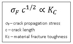
This is considered a type of zero-load aging (do Nascimento, et al. [2]), because it can occur even in the absence of an applied stress. The addition of new surface flaws and the gradual increase in crack length with time both strongly influence the bulk mechanical properties. The general equation for crack propagation and failure length is [2]:

Following that the fracture toughness is a material constant, as the crack length increases with time the crack propagation stress will decrease and the mechanical strength of the fiber will follow. For example, do Nascimento and Lepienski show a decrease in fiber resistance from 4.1 GPa to 2.9 GPa over four weeks at 85°C and 85% humidity.
(c) Explain how do Nascimento and Lepienski [2] calculated the fracture stress for glasses subjected to Berkovich indentation in Table 1. What was the point of using the indenter in this experiment? If they were instead to indent the fiber sufficiently to attain the fracture stress by loading the fiber surface with a Berkovich diamond indenter, state the corresponding indentation loads and depths for the pristine and maximally aged fibers.
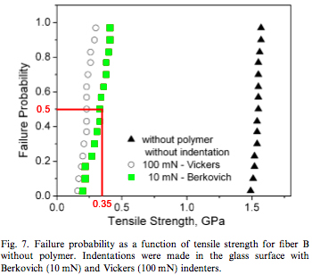
The fracture stresses in Table 1 [2] were obtained using a tensile test. The indented fibers were subjected to a tensile load of 100N, with displacement rates of 0.5, 5, 50 and 500 mm/min until failure. The failure probability was then plotted versus the tensile stress. The fracture stress in Table 1 is then taken to be equal to the tensile stress corresponding to a 50% failure probability. For example, for 10 mN Berkovich indented fibers, the fracture stress is found to be 0.35 GPa:

Courtesy of Elsevier, Inc., Science Direct. Used with permission.
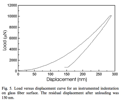
The point of using an indenter in this experiment is to be able to make cracks of known and controlled depth. Using a 10 mN load with a Berkovich indenter, do Nascimento and Lipienski obtained an indentation depth of 150 nm, as shown in this load vs. displacement curve:

Courtesy of Elsevier, Inc., Science Direct. Used with permission.
These 10 mN Berkovich indentations were then used as a reference to calculate the indentation depths for the other fibers and estimate the crack size for the water aged fibers. Using the equation K/ψ = σ√c, with a fracture load σ = 0.35 GPa and an indentation depth c = 150 nm (values for the reference indentations), the authors of the paper find the ratio K/ψ to be equal to 0.13 MPa√m. Since this ratio is constant for a given material, they are then able to estimate the typical flaw size in other fibers from the fracture stress.
Let’s now suppose that they performed another experiment, where they indented the fiber sufficiently to attain the fracture stress by loading the fiber surface with a Berkovich diamond indenter. To calculate the applied stress of a Berkovich indenter, we need to know the applied force and the applied area. In nano-indentation the depth of penetration is measured as the load is applied. Knowledge of the geometry of the indenter allows for the calculation of the contact area as a function of penetration depth. This calculation is done below, using the standard Berkovich indenter geometry:
Image removed due to copyright restrictions. Please see slide 28 in Kim, Do Kyung. “Nanoindentation: Lecture 1 Basic Principles.” (PPT)
From the relation σ = F/A and the above expression of A as a function of h, we can deduce the following equation for the indentation depth as a function of the fracture stress and the indentation load:

Assuming an indentation load of 10 mN, we can estimate that the indentation depth for pristine fibers is 315 nm (with σ = 4.1 GPa) and that for 4 weeks aged fibers it is 381 nm (with σ = 2.8 GPa).
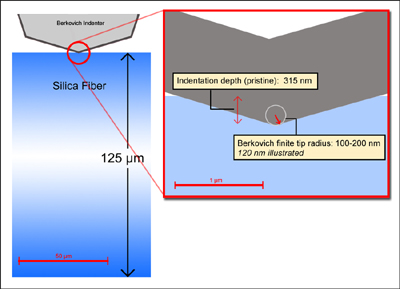
(d) Graphically represent a cross-sectional view of this proposed fracture stress experiment on the fibers, considering the relative lengthscales of the fiber, the depth of indentation corresponding to fracture noted in your calculations for (c), and the finite radius of diamond Berkovich indenter probes.

Image made using Photoshop. Finite tip radius as calculated by [3].
References
[1] Michalske, T. A., and B. C. Bunker. “Slow Fracture Model Based on Silicate Fracture Models.” Journal of Applied Physics 56 (November 15, 1984): 2686-2693.
[2] do Nascimento, E. Mauro, and C. M. Lepienski. “Mechanical Properties of Optical Glass Fibers Damaged by Nanoindentation and Water Ageing.” Journal of Non-Crystalline Solids 352 (2006): 3556-3560.
[3] Yu, Ning, Andreas A. Polycarpou, and Thomas F. Conry. “Tip-radius Effect in Finite Element Modeling of Sub-50 nm Shallow Nanoindentation.” Thin Solid Films 450 (March 1, 2004): 295-303.
Plasticity and fracture of microelectronic thin films/lines
Effects of multidimensional defects on III-V semiconductor mechanics
Defect nucleation in crystalline metals
Role of water in accelerated fracture of fiber optic glass | Problem Set 2 | Problem Set 3 | Problem Set 5
Carbon nanotube mechanics
Superelastic and superplastic alloys
Mechanical behavior of a virus
Effects of radiation on mechanical behavior of crystalline materials


