(b) Considering Ivanovska, et al.’s Fig. 1E [1] rendering of a bacteriophage prohead “shell”, compute the stress required to initiate plastic deformation if the prohead were considered to be a short cylindrical shell under uniaxial compression.
Ivanovska, et al. [1] states on p. 7604 of the manuscript that proheads responded linearly to indentation forces up to approximately 2.8 nN. Define this as Fyield. From this, we can calculate the stress required to initiate plastic deformation, σy, based on the cross-sectional area A. In other words, we’re given Fyield = 2.8 nN; and σy = Fyield/A.
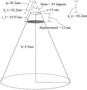
Finding cross-sectional area A: The manuscript states that the cantilever used was OMCL-RC800PSA from Olympus. Based on the manufacturer specifications [2], the probe is a sharpened pyramidal tip, but we’ll approximate it as a cone here with a tip radius r = 15 nm, tip angle θ = 45°, tip height h = 2.9 μm (Fig. 1). Because the prohead and cantilever are of comparable sizes, we cannot model the prohead surface area being acted upon as a flat plane. Thus we cannot simply take the tip area to be our cross sectional area. Our actual cross-sectional area is the projected contact area (shaded region in Fig. 1). Therefore, using cone geometry, we can find A via A = π(r1)2, where r1 is as indicated in Fig. 3. To calculate this, we need to know the strain at yield point, which is provided by the manuscript (pg. 7604): strainyield = maximum linear displacement = 12 nm. Using trigonometry, we’re able to find the following value: r1 = 19.97 nm. Therefore, A = 1252.2 nm2.

Fig. 1. Cantilever Probe Tip. Dimensions based on manufacturer specifications of OMCL-RC800PSA from Olympus. Tip is approximated as a cone with tip radius r, tip height h and tip angle theta. Shaded region indicates cross sectional area used for yield stress calculation.
Finding σy: σy = 2.8 nN / (1252.2 nm2) = 2.2 MPa
(c) These authors [1] state that imaging of the proheads in contact mode atomic force microscopy (AFM) allows for the study of prohead deformation under “uniaxial pressure.” This is incorrect at several levels. Develop a brief, justified objection to this claim, considering the design of the experiment in detail.
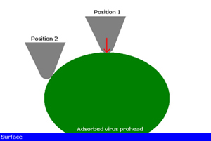
The authors used scanning force microscopy (SFM) to image the proheads under different maximal loading forces and assumed this to be “uniaxial pressure”. However, given the imaging modality rasters an AFM tip, with a contact region of approximately 5 nm, across the virus prohead, which itself has an inherent curvature, the applied force is clearly not uniaxial, see figure below. Along the curvature of the virus prohead the applied force is resolved into various components. Also, the size of AFM tips (< 20 nm) are on the order of the size of a prohead and thus cannot be considered as a point load when forces are applied to the prohead.

(d) These authors also claim that the mechanical testing of such proheads enables prediction of the elastic properties of the bacteriophage, by recourse to nonlinear elastic bucking of shells. Based on the data they present in this paper and known continuum mechanical analysis of shell elasticity, is this claim justified? Timoshenko [5] is an excellent resource on mechanical analysis of shells.
The authors do nanoindentaion of the bacteriophage φ 29 shells and then model the shells using a continuum approach, assuming it is homogeneous and a thin shell. However, as we know the shell’s microstructure is inhomogeneous and they even admitted there is a bimodal distribution of elastic moduli. Also, the authors considered the shells as spherical thin shells, assuming h/R = 0.1. In order to be regraded as flat plates (thin shells), the shells may have the thickness (h) which is less than one hundredth of the least radius (R) of curvature [3]. This means that the nonlinearity of the shells can be reduced to the solvable linear shells [4]. If the ratio of the thickness to the radius is comparable to the one tenth like this case, the shells may be considered as the moderately thick shells. In thick shells, the interaction due to bending term and stretching term cannot be evaded. Therefore, their claim would not be justified.
References
[1] Ivanovska, I. L., P. J. Pablo, B. Ibarra, G. Sgalari, F. C. MacKintosh, J. L. Carrascosa, C. F. Schmidt, and G. J. L. Wuite. “Bacteriophage Capsids: Tough Nanoshells with Complex Elastic Properties.” PNAS 101 (2004): 7600-7605.
[2] Micro Cantilever.
[3] Cox, H. L. The Buckling of Cylindrical Plates and Shells. New York, NY: Pergamon, 1963, pp. 71-72.
[4] Gould, Phillip L. Analysis of Shells and Plates. Upper Saddle River, NJ: Prentice Hall, 1998, pp. 461-463. ISBN: 9780133749502.
[5] Timoshenko, S., and S. Woinowsky-Krieger. Theory of Plates and Shells . New York, NY: McGraw-Hill, 1959.
Plasticity and fracture of microelectronic thin films/lines
Effects of multidimensional defects on III-V semiconductor mechanics
Defect nucleation in crystalline metals
Roleof water in accelerated fracture of fiber optic glass
Carbon nanotube mechanics
Superelastic and superplastic alloys
Mechanical behavior of a virus | Problem Set 2 | Problem Set 3 | Problem Set 5
Effects of radiation on mechanical behavior of crystalline materials


