
By Prof. Leah Buechley, High-Low Tech group. (Courtesy of Leah Buechley. Used with permission.)
We’ve developed a construction kit that lets people create interactive paintings. The kit consists of conductive paint, a small magnetic “tearDrop” computer, a magnetic speaker, several lights (light emitting diodes or “LEDs”), and a few other things. Here’s what it looks like:
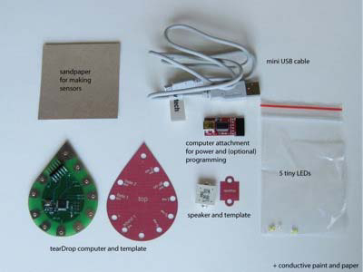
Paper computing construction kit.
We’ll use glue and conductive paint to create circuits with lights that will be controlled by the tearDrop computer. We’ll use pencils and conductive paint to build sensors and switches that will make our paintings interactive. To attach our tearDrop to our electric paintings, we’ll rely on the fact that it is magnetic. We’ll put our painting on a magnetic surface like a refrigerator, a piece of steel, or a sheet of magnetic paper and then the tearDrop computer will stick to it, completing electrical connections between the painted circuitry and the computer. Here’s a movie of a design I made:
- Sketching circuits with the paper computing kit (MOV - 19.4MB)
Before you get started with the project, you should know some basic stuff about the materials we’re working with.
About Conductive Paint
We will be using a water based paint that contains conductive copper particles. The paint is nontoxic and can be cleaned up with soap and water. There are three very important things to know about working with this paint:
- the paint is not conductive until it dries.
- you need to thoroughly mix the paint each time you use it. you can do this by vigorously shaking your bottle.
- you should use the paint as quickly as possible. copper + water + oxygen = oxidized non-conductive copper. the paint will quickly corrode in its (non-airtight) container, turning green and then black, losing its conductivity in less than a week. once the paint is dry this is no longer a problem, it’s only in the bottle that the paint oxidizes.
About Circuits and LEDs
If you are completely new to circuits, you should read enough to understand how a basic circuit works before embarking on this project. Good introductions to electricity and circuits can be found at Electronics Club - Electricity and the Electron and Doctronics - Circuits.
We’re going to be using Light Emitting Diodes or LEDs in our painting. LEDs are highly efficient lights that come in an assortment of colors, shapes and sizes. If you are new to LEDs, you should read the first section of the page at: Electronics Club - Light Emitting Diodes (LEDs) before proceeding.
Unlike some lights, LEDs have two different ends, a positive (+) end, called the “anode”, and a negative (-) end called the “cathode”. The negative end of the LEDs in the kits are marked with lines on their bottom.
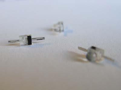
Kit LEDs, with stripe indicating the negative end.
To get an LED to turn on you need to attach its positive end to the positive end of a battery or other power source (like our tearDrop computer) and its negative end to the negative end of the battery or other power source. In the case of the tearDrop there are two negative attachment points, the tabs labeled “-” on the tearDrop template, and five positive attachment points, the tabs labeled “+”, “fade1”, “fade2”, “on 3” and “on all”.
A note about LEDs and resistors: generally, you have to be careful not to attach an LED directly to a power supply. Attaching an LED directly to a power supply can cause the LED to burn up as too much electrical current flows through it. Normally, you have to attach an LED to a power supply through an electrical component called a resistor. However, for this project we don’t need resistors because the conductive paint we’re using has some natural resistance. For more information on resistors and LEDs see Electronics Club - Light Emitting Diodes (LEDs).
About the TearDrop and Arduino
If you want to re-program your tearDrop, read this section, which provides a whirlwind introduction to programming the tearDrop. Otherwise, you can skip to “Getting started”
The tearDrop computer is an Arduino and can be reprogrammed using the Arduino software, which you can download for free here. There are instructions for installing and configuring the software here. In following these instructions mentally replace every instance of LilyPad with tearDrop. (Note: in step 6, “Select the right board”, you should select “LilyPad Arduino w/ ATmega168”).
Before you start trying to program the board, read through this guide that will give you an introduction to Arduino program structure.
Start your experimenting by going through this basic tutorial which blinks the LED on the tearDrop board. Now for some more specific tearDrop information and examples.
The tearDrop has only 8 input and output pins, in contrast to the traditional Arduino, the Arduino Duemilanove, which has 20. The Arduino labels for the tearDrop pins are printed on the tearDrop board. They are: 1 (tx), 0 (rx), a3, a2, a0, a5, 11, and 10. We’ll need to use these labels, and not the labels on the template, when we write Arduino code.
readData.txt (TXT) is a simple program that reads sensor data from pin a3 and then sends that data back to the computer as a number from 0 to 1023. To try this example, copy the text from the readData.txt file, paste it into an Arduino window and download the code to the tearDrop using the technique from the first example. Attach a sensor to pin a3 and then click on the right most icon at the top of your Arduino window. (The icon looks a bit like a camera and text saying “Serial Monitor” will appear when you hover over it.) This will open the “serial monitor”, a window where you can see sensor data that is sent from the tearDrop to the computer. For more information, read this tutorial about a similar example.
tearDropExample.txt (TXT) is the program that corresponds to the tearDrop template and the rest of the text on this page. It maps input from a3 (sensor1 on the template) to output on pin 11 (fade1 on the template), etc. To try this example, copy the text from the tearDropExample.txt file, paste it into an Arduino window and download the code to the tearDrop.
For more information about Arduino, see the Arduino language reference and Limor Fried’s excellent tutorials. Note: when you are sending data back and forth from the tearDrop to the computer, pins 0 and 1 (“on3” and “on all” on the template) won’t work because they are attached to the communication lines.
Getting Started
The tearDrop computer has three inputs for switches or sensors, one output for sound, two fading outputs that fade lights on and off and two on/off outputs that just turn lights on and off. It is preprogrammed so that “sound 1” changes in response to sensor 1, “fade 1” dims and brightens in response to sensor 1, “fade 2” dims and brightens in response to sensor 2, “on 3” turns on in response to sensor 3, and “on all” turns on when all three sensors are fully triggered.
The kit includes a template with labels for each of the inputs and outputs. The top of the template corresponds to the top of the tearDrop (the side with all of the electronics). Sensor inputs are labeled with inward pointing arrows and LED and sound outputs are labeled with outward pointing arrows. The template lets you see the mapping of the tearDrop’s behavior and also provides a physical template for the tearDrop that will help you with your painting. Here’s a close-up of the tearDrop and its template:
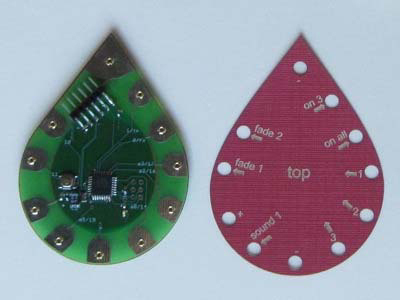
Close up of the tearDrop Arduino.
You may want to plan out your complete design before you get started, or you may want to start by experimenting. Whichever path you choose, once you’re ready to start painting, the first thing you want to do is decide where on your sheet of paper you’re going to put the tearDrop. Once you’ve decided, place the tearDrop template on the paper and use a pen or pencil to draw out and label its footprint.
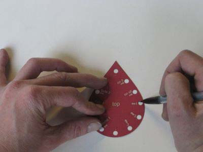
Tracing the tearDrop on paper.
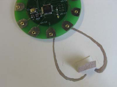
Then, with a pen or pencil, draw out a path for one LED. One side of your LED must lead back to one of the negative pads on the tearDrop (one of the pads marked with a minus sign “-”) and the other side of your LED should lead back to either the positive pad on the teardrop (the one marked with a plus sign “+”) or one of the “fade” or “on” outputs.
I’m drawing a path for an LED between + and - on the tearDrop. This is a nice way to start your design because an LED between + and - will always be on. Since the LED will always be on, you’ll get a feel for the materials without having to worry about making a sensor or a switch, which are necessary to trigger the “fade” and “on” outputs on the tearDrop.
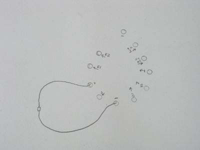
Path for an LED between + and -.
Attaching a Light
To attach a light, you’ll glue it down and then use conductive paint to link it to the tearDrop computer. To add a light to your painting, first glue it down to the page (super glue works especially well), and bend the legs of the LED down so that they’re touching the paper like so:
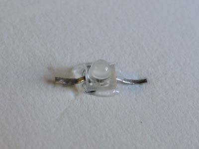
LED with bent legs glued to the paper.
Then paint over the legs of the LED with your conductive paint like so:
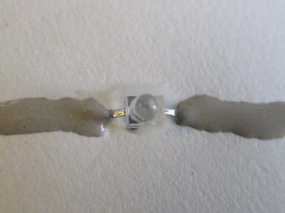
Conductive paint connecting to the LED leads.
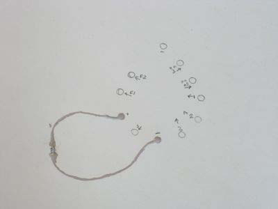
The painted LED connection between + and – on the tearDrop.
Once you’ve painted the circuit you have to wait for the paint to dry before the LED will come on. So, now you have to wait for the paint to dry. You can work on other design elements like switches and sensors while you wait.
After 15-30 minutes the paint should be dry and you can test out your LED circuit.
Note: speakers can be attached in basically the same way as LEDs only you don’t have to worry about negative and positive sides of speakers. You simply attach one side of the speaker to a “-” tab and the other to the “sound 1” output tab.
Adding a Switch to Your Painting
To make a switch, we connect one of the pads marked with a minus sign “-” temporarily to one of the sensor inputs. Below for example is one way to make a switch for sensor 3. There is one painted line leading to “-” and one painted line leading to sensor 3. When these two lines are connected with a third piece of painted paper, the switch is closed and output “on 3” turns on. To make this example I painted the “-”, “sensor 3”, and “LED 3” traces, and a small piece of paper. Then I waited for the paint to dry, and in about a half an hour had a working circuit:
Adding a path for a switch made of painted paper.
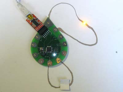
With the switch closed, the LED lights.
Adding a Sensor to Your Painting
A sensor is similar to a similar to a switch, but slightly more complicated. To create a sensor, we connect one of the pads marked with a minus sign “-” to one of the sensor inputs through a changing resistor. A resistor is a material that resists the flow of electricity and the tearDrop can detect how much electricity is getting through a resistor. When the value of the resistor changes, the amount of electricity changes, and the tearDrop can detect this change. It turns out that pencil lead or graphite is a good resistor, so we’ll rely on it to build sensors.
To build a sensor we want to vary the value of the resistor somehow. A good way to vary the value is to shorten or lengthen our graphite resistor. A longer line has more resistance and a shorter one has less resistance. Here’s a sketch of a sample sensor where we are shortening and lengthening a graphite resistor by moving a sensor input tab across its surface. Note how one end of the resistor is attached to ground and the moving input tab is attached to a sensor input, in this case “sensor 2”.
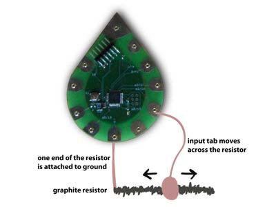
Building a sensor by using a variable resistor.
Here’s an example of an actual paper sensor. In this image, when we move the blue tab (whose underside is painted with conductive paint), we change the length of graphite between the blue tab, the input tab, and the left side of the graphite sphere, which is attached to ground.
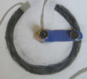
An actual paper sensor.
This creates a sensor that can detect rotation.
Making a Complete Project
Now your job is to build an interactive painting that incorporates input and output.
Inspirations and References
Drawdio: A Pencil That Lets You Draw Music (Jay Silver)
Pulp-Based Computing (Marcelo Coelho and Pattie Maes in collaboration with Joanna Berzowska and Lyndl Hall)


