
All images courtesy of Alex Slocum.
System Overview
The picture below is a schematic overview of the whole system. Two batteries supply power to the control box. The control box distributes that power to the four actuators based on commands it receives from the transmitter. The transmitter receives commands from joysticks/throttles via the microprocessor. For the details of each sub-system, please consult the appropriate sub-section of this page.
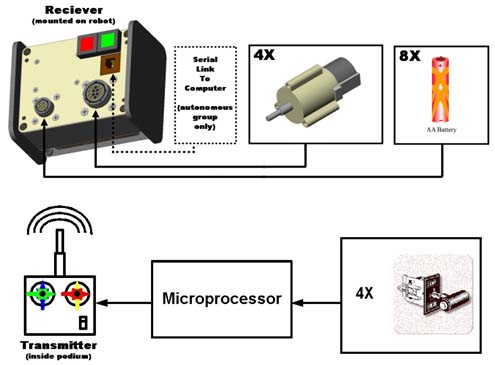
Control box system schematic.
Wiring Your Machine
The above figures indicate how to wire both the Amp 14 pin connector (to connect to your motors) and the 4 pin connector (to connect to your batteries). Please obtain the pin and lead wire (PDF) spec from the fastener cabinet. Pay particular attention to how the batteries are wired! This wiring layout is not done arbitrarily - if the battery plug is wired incorrectly, either the control box will not turn on, or worse, the batteries will short within the plug, which will damage the control box and possibly cause your your batteries to explode!
Incorrectly wiring either plug will result in damage to your machine, batteries, and control box!
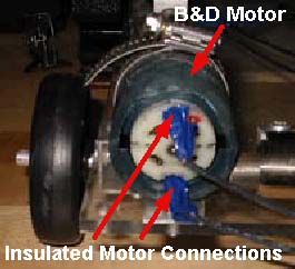
Motor connection photo.
All wiring must be insulated. This includes wire splices, soldered connections to the battery cradles, and connections to actuators. This is most easily done with electrical tape, though most securely done with heat shrink tubing. Poorly insulated connections are a confirmed source of controller problems.
The staff will not assist with machine debugging until all connections are properly insulated. Machines without properly insulated connections are barred from competition
The Control Box
Recommended: Download the Solidworks 2001 solid model of the control box: Control_Box.zip (ZIP - 2.0MB) (The ZIP file contains: 25 .sldprt files, 3 .sldasm files, and 1 .swj file.)
Contained within the zip file are two different versions of the solid model - one high quality version and one low quality. For almost all purposes of 2.007, the low quality version will suffice. It contains all the necessary dimensions while keeping the computer’s required processor speed to a minimum. The high-quality version, however, serves as a useful example of some of the advanced features of Solidworks.
While we have striven to make all the boxes identical to each other and the solid model, some variation is inevitable, however, and it is the student’s responsibility to account for it.
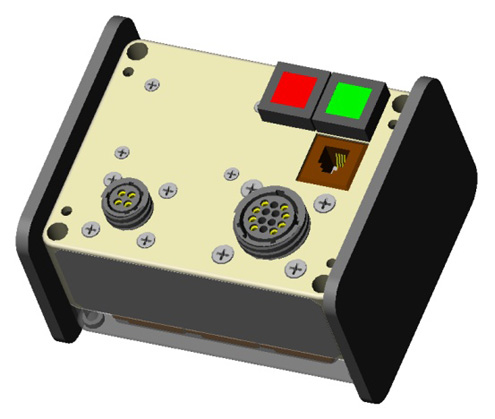
Control box image 1.
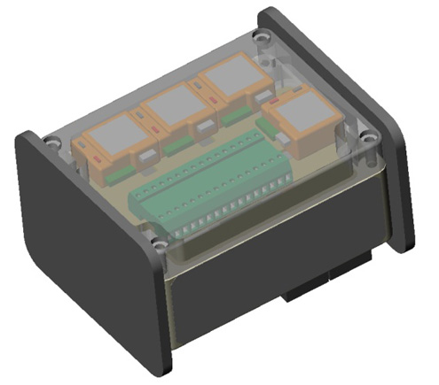
Control box image 2.
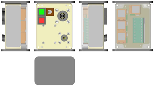
3 views on control box image.
Control box 2-button image.
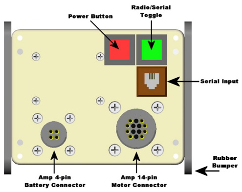
Features
- Power Button - Activates and de-activates the unit. Will glow red when the the batteries are connected and the switch is on. This button will mostly be used during the contest. See the Contest Plan for more information. While the control box is mounted to your machine, the Power switch must be easily accessible by a staff member.
- Radio/Serial Toggle - This switch determines which input the control box will listen to. If the switch is NOT illuminated, the box will only listen to its radio receiver, thereby allowing the podium joysticks to control the motors on the robot. If ths switch is illuminated, the control box will listen to its serial input (phone jack) for commands to forward on to the speed controllers. Only the autonomous group will be using the serial input! If you are using the podium (radio) and the box is not responding, check to make sure this switch is off (not illuminated).
- Serial Input - This input uses a standard phone jack to input serial commands to the speed controllers. This is used only by the autonomous group. For more information as to the protocol for serial communication and the wiring diagram for the phone cable, see the MiniSSC page here. (PDF spec)
- Rubber Bumpers - It is likely the control boxes will be dropped. Please try to avoid this, but as it will certainly happen, the rubber bumpers are there to damp the impact.
- AMP 14-pin Motor Connector - Generously donated by Tyco Electronics, this is where your motors are plugged into the control box. It too must be easily accessible when the control box is mounted on your machine. The connector is the most vulnerable part of the control box. It must be protected against impact. See the wiring diagram above to correctly wire up your mating plug.
- AMP 4-Pin Battery Connector - Generously donated by Tyco Electronics, this is where your batteries are plugged into the control box. It too must be easily accessible when the control box is mounted on your machine. The connector is the most vulnerable part of the control box. It must be protected against impact. See the wiring diagram above to correctly wire up your mating plug.
- Light Emitting Diodes - Each Novak Spy Electronic Speed Control (under the control box’s clear lid) has a light emitting diode (LED). The LED glows solid red when the speed control is in neutral and transmitting no power to the attached actuator. The LED glows solid green when the ESC is driving the actuator “full-forward”, and the LED blinks green when the ESC is driving the actuator “full-backward.”
- Steel Mounting Plates - Mounted to the sides of the control box are thin strips of steel sheet metal. It is recommended that you use one or both of your magnets to mount the control box to your machine via these steel plates. You are responsible for designing the mounting mechanism to be robust enough to keep the control box attached to your machine throughout the contest. Magnets alone will not secure the control box in the presence of large inertial forces e.g. the impact forces associated with a fall.
- Control Box Approximate Weight - .95 lbs. (0.885 kg.).
Mounting Checklist
- Power switch must be easily accessible by a staff member.
- Radio/Serial toggle switch only illuminated for autonomous control!
- The ESC’s LEDs should be visible for debugging (optional but recommended).
- Amp connectors must be easily accessible by a staff member.
- Magnets will not secure the control box in the presence of large inertial forces.
- The amp connectors must be protected against impact.
Student Interface
Students will control their machines with four joysticks/throttles. The channel each joystick controls is indicated by color. If you like, you can think of pushing the throttle handle away from you as “forward,” and pulling it towards you as “backward,” with null point in between, but what “forward” and “backward” mean for a machine is governed by how the AMP plug is wired. See the wiring section for more information. Full forward corresponds to approximately 6.0V (voltage depends on loading and state of charge) across the motor terminals, and full backward corresponds to -6.0V across the motor terminals.
“High” and “Low” have no meaning. No functionality is associated with the buttons at this time.
Remember, driving 2.007 machines is difficult. Plenty of time should be allocated for practice.
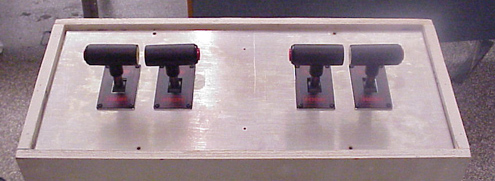
Control podium image.
Transmitter box diagram.
If the joystick system is unavailable, machines may be driven from the Futaba transmitter directly. The figure above identifies the channels and directions. Please confirm the transmitter matches the control box.
Contest Plan
The contest will use eight control boxes and two spares. Each table will have four control boxes. Those four control boxes will be set to only two different frequencies. Two control boxes will share each of the four frequencies. As in previous years, the tables will have color coded starting regions. One table will be blue and orange. The other will be red and yellow. Each color starting zone will be assigned a frequency. The table below summarizes this.
| TABLE ONE | TABLE TWO | ||
|---|---|---|---|
|
Blue “A” Blue “B” X1 Mhz. |
Orange “A” Orange “B” X2 Mhz. |
Red “A” Red “B” X3 Mhz. |
Yellow “A” Yellow B" X4 Mhz. |
To keep the contest going at a good clip, control boxes will be installed in the pit area. To prevent machines from running wild in the pit area, the boxes installed there (the “B” set for example), will be left off. Only when machines are placed on the table and about to start will their control boxes be turned on. After a contest, control boxes will be returned to the pit area to repeat the cycle.
Calibration Procedure - Reference Only
From the Novak Reactor Reversible Manual:
- Turn on the transmitter
- Turn on the speed control
- Press and hold the ESC’s one-touch button - With the transmitter throttle at neutral, press and hold the speed control’s One-Touch button until the status LED turns solid red.
- Release ESC one-touch button when LED is red
- Pull throttle to full-forward position - Hold it there until the status LED turns solid green.
- Push throttle to full-reverse position - Hold it there until the status LED blinks green.
- Return transmitter throttle to neutral - Status LED will turn solid red, indicating that throttle is at neutral and proper programming has been completed.
- Check operation of the speed control - With no throttle or brake applied the status LED should be solid red and the motor should not be running. At full-throttle position the status LED should be solid green and the motor running at full speed. At full-reverse position the status LED should be blinking green and the motor should be running full speed in reverse.


