
All images courtesy of Alex Slocum.
How to Wire Your Machine
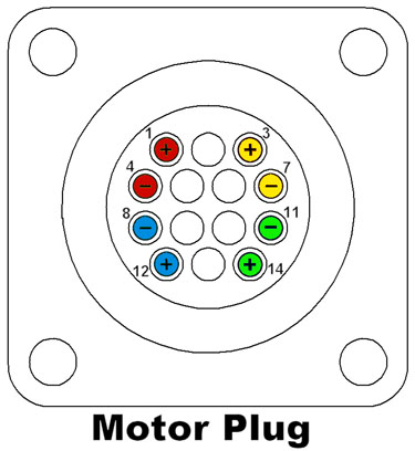
Motor plug.
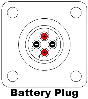
Battery plug.
The above figures indicate how to wire both the Amp 14 pin connector (to connect to your motors) and the 4 pin connector (to connect to your batteries). Please obtain the pins and lead wire (PDF) from the cabinet. We recommend that you print out the debug sheet (PDF) and bring it to lab. Pay particular attention to how the batteries are wired! This wiring layout is not done arbitrarily - if the battery plug is wired incorrectly, either the control box will not turn on, or worse, the batteries will short within the plug, which will damage the control box and possibly cause your batteries to explode!
Long motor and battery wires have the following two problems. Try to keep them short for your own benefit.
- Longer wires increase the resistance, and therefore reduce the power going to the motors.
- Longer wires and improperly soldered wires can cause spurious signals on the radio link. These spurious signals will cause your machine to jitter or jerk around when you are not touching the control box.
You may not wire two motors in parallel to one channel!
Incorrectly wiring either plug will result in damage to your machine, batteries, and control box!
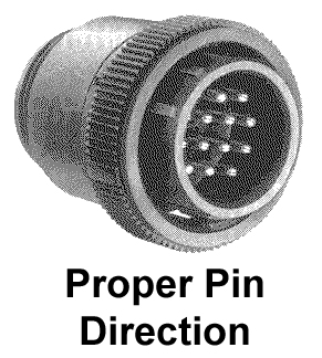
Proper pin direction.
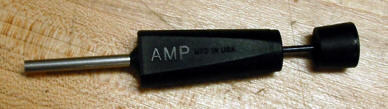
AMP pin removal tool.
When wiring the connectors, check to make sure that the pins are pointing in the proper direction, which is shown above. You can use the AMP pin removal tool to remove pins and insert them properly.
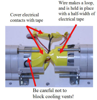
Carefully insulated wires.
All wiring must be insulated. This includes wire splices, soldered connections to the battery cradles, and connections to actuators. This is most easily done with electrical tape, though most securely done with heat shrink tubing. Poorly insulated connections are a confirmed source of controller problems.
All wiring should be strain relieved. Strain relief can be created by looping wire then securing it in place using electrical tape, zip ties, cable mounts, velcro, etc.
The staff will not assist with machine debugging until all connections are properly insulated.
Machines without properly insulated connections are barred from competition!
Machines that are barred from competition cannot compete in the contest, which means you cannot receive any points for the contest. This is very bad!
About the Batteries
For the contest, you will be using the batteries supplied with your handheld drill. The drill you are receiving is a 14.4V cordless drill. The batteries are fairly hefty NiMH batteries. The nominal voltage of the battery is 14.4 Volts, although the battery can supply between 12 and 17 Volts, depending on the charge. Do not run your battery below 12V, as it will begin to damage the battery. The control box will signal when you have dropped below 12V and will shut off at 11V.
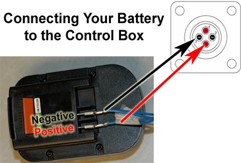
Connecting battery to control box.
Note: Your battery may look different. Check the polarity of your leads before connecting the battery to the control box.
To connect your battery to the control box, you need to create a power cable using two of the pin and lead wires in the cabinet. Put two wires into the AMP 4-pin power connector in the appropriate numbered holes. Attach 1/4" spade connectors to the other end of the wire. These connectors are available in the cabinet or at your local hardware store. The screw-on style battery spade plugs are not the best solution. The best option is to use crimped plugs and flow in some solder between the plug and wires. If the wires attached to the connector are not long enough for your design, you can solder additional wire onto these leads. Check with a UA or the shop staff for help soldering. Remember that these solder joints must be insulated!
Please pay careful attention to the order of the wires when connecting the power cables to avoid plugging things in backwards. You should label your wires positive and negative. Or a better solution is to design a custom connector that will only fit onto the battery one way. You can also create a nice battery holder using the 3" box extrusion by milling out a slot on the wide face so that the battery can slide along the length. Fix the spade connectors at the end of the extrusion. Add some velcro or a locking feature and you have a nice secure battery holder!
Charging the Batteries
It is your responsibility to keep your batteries properly charged during the semester and during the contest. Please read the instructions on how to charge your battery, which were included in the drill kit. Several charge/discharge cycles are required before you can charge your battery to its maximum capacity.
The batteries will slowly loose charge when they are not connected to the charger. Read the instructions included with the charger to determine when there may be problems with your battery or charger. Do not let the battery get hot during charging. If it does it will get damaged.
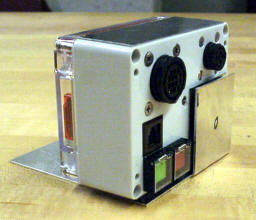
About the Control Box
Recommended: Download the Solidworks 2003 solid model of the control box: Control_Box.zip (ZIP) (The ZIP file contains: 8 .sldprt files, 1 .sldasm file, and 1 .swj file.)
While we have striven to make all the physical boxes identical to each other and the solid model. Some variation is inevitable, however, and it is the student’s responsibility to account for it. Approximate weight of the control box is 0.85 lbs. (0.39 kg.). Dimensions of the box can be obtained from the solid model.
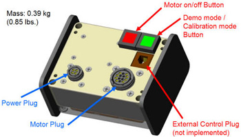
Box front.
Features on the Box Front
- Motor on/off Button - Activates and de-activates the unit. Will glow red when the the batteries are connected and the switch is on. This button will mostly be used during the contest. While the control box is mounted to your machine, the Power switch must be easily accessible by a staff member.
- Demo/Calibration Mode Toggle - This switch will put the box into a demo mode or a calibration mode. The button will glow green when it is activated. When it is activated, the system will not respond to commands from the podium. DO NOT USE THIS BUTTON!! If you notice the podium controls are not zeroed properly (motion when the controls are not touched), contact a 2.007 staff member to have the box recalibrated.
- External Control Plug - The control box can be programmed to listen to instructions over its serial input (phone jack) for commands to forward on to the speed controllers. Only autonomous machines will require the serial input! No one currently has autonomous machines, so this feature is not activated.
- AMP 14-pin Motor Connector - Generously donated by Tyco Electronics, this is where your motors are plugged into the control box. It must be easily accessible when the control box is mounted on your machine. The connector is the most vulnerable part of the control box. It must be protected against impact. See the wiring diagrams to correctly wire up your mating plug.
- AMP 4-Pin Battery Connector - Generously donated by Tyco Electronics, this is where your batteries are plugged into the control box. It must be easily accessible when the control box is mounted on your machine. The connector is the most vulnerable part of the control box. It must be protected against impact. See the wiring diagrams to correctly wire up your mating plug.
- Steel Mounting Plates - Mounted to the sides of the control box are thin strips of steel sheet metal. It is recommended that you use one or both of your magnets to mount the control box to your machine via these steel plates. You are responsible for designing the mounting mechanism to be robust enough to keep the control box attached to your machine throughout the contest. Magnets alone will not secure the control box in the presence of large inertial forces e.g. the impact forces associated with a fall.
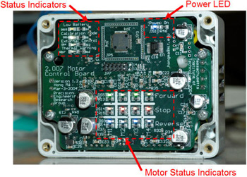
Box back.
Status indicator.
Motor status indicators.
Features on the Box Back
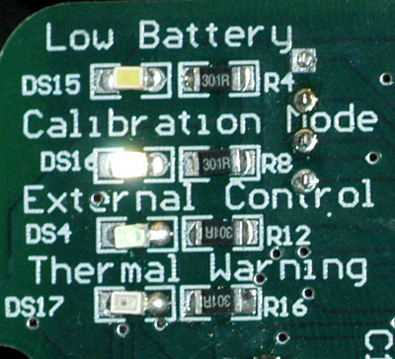
- Status Indicators - The lights in the status indicators group describe operation of the control box:
- Low Battery - The Low Battery LED turns on when battery voltage dips below 12V. Motor output is turned automatically off when battery voltage dips below 11V to protect the batteries.
- Calibration Mode - Occasionally (maybe once a year), the control system will go out of calibration. When the system is out of calibration, the control box will send power out to the motors when the joysticks are at zero. When this happens, see a UA or a staff member to get the control box recalibrated. When the system is being calibrated, the Calibration light will be steady.
- External Control - This LED indicator will turn on when an external programmable controller sends signals to the control box instead of the podiums. This feature is not currently used in 2.007, so this LED will not be lit.
- Thermal Warning - The Thermal Warning LED will turn on when the internal temperature of the motor drivers reach 140°C. This high temperature usually requires stalling the motors for >35s. Beware of damage to your motor! The motor drivers will be automatically shutoff at 170°C. To assist in cooling the control box, a CPU fan will run. This fan requires that the cooling vents on the sides of the box be unobstructed. Your machine will not be allowed to compete if these vents are blocked!
- Power LED - This LED will be lit when power is supplied to the box using batteries or using the podium power supply.
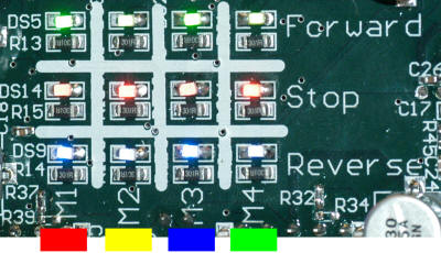
- Motor Status Indicators - These 12 indicators will show the status of each motor associated to the controller’s four channels (eg. the Red channel on the podium corresponds to the first column on the control box).
- Green Light = Forward on Channel
- Red Light = Stop on Channel
- Blue Light = Reverse on Channel
If the lights are blinking in a pretty fashion, the control box is in Demo Mode. To shut off demo mode, push the green button on the front side of the box.
How to Mount the Control Box
Checklist
- The red and green buttons must be easily accessible by a staff member.
- The status LEDs should be visible for debugging (optional but recommended).
- AMP connectors must be easily accessible by a staff member.
- Magnets will not secure the control box in the presence of large inertial forces. If you plan on making any form of attacking robot, you must ensure that the control box will not come loose. Magnets will not be sufficient for this purpose!
- The AMP connectors must be protected against impact.
- The cooling vents on the control box must be unobstructed.
Note: When using the control box in the lab, do not leave it on the table or you may lose the right to use it. Return it to the magnet on top of the podium.
Suggested Mounting Hardware
Suggested mounting hardware.
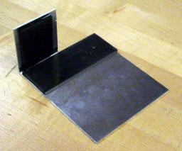
Suggested mounting hardware.
Process Plans to Create the Mount
- Shear two piecies of the 1/8" thick adhesively backed magnet. The larger piece is 1.5" by 4." The smaller piece is 1.5" by 2."
- Shear out a piece of sheet metal according to this drawing. (PDF)
- Bend the sheet metal. Make sure you bend the metal in the correct direction (see picture).
- Use the adhesive on the back of the magnets to assemble the mount according to this drawing. (PDF)
- If you are creating an attacking robot, you may need to add a velcro strap or an additional feature to prevent control box detachment.
This is by no means the only way to mount the control box. It is just a way. We do not guarantee the mount. You will have to make sure it is suitable for your particular machine. It is also likely the mount will need to be modified to better suit your machine. Please feel free to do so and try to integrate it with another sheet metal structure. To attach the mount to your machine, we recommend double sided tape or screws. When using screws, make sure they do not interfere with the mating of the control box and the magnets.
Wires, rubber bands, and string are not sufficient mounting solutions for the control box. Rubber bands, string, and velcro may be used in conjunction with the above design, but not independently.
If the control box comes loose during the contest, your machine will be immediately disqualified.
No questions asked and no second chances!
How to Run the Control system
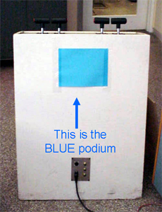
Blue podium.
-
Get a control box. Match the color on the control box to the color on the front of the podium.
-
Connect power to the control box through the AMP 4-pin connecter, either using the power supply in the podium or your batteries. To connect to the podium power supply, simply connect the tether cable on the front of the podium to the box. Be sure to check that your machine runs with batteries too.
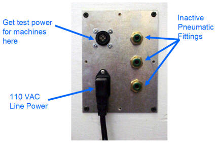
Connecting power.
-
Make sure power on the control box is off. The control box is off if both the red and green buttons are not lit.
-
Connect the motor signal cable to the control box using the AMP 14-pin connector.
-
Turn on the control box by pressing in the red button. Do not press the green button.
-
Check the status of the indicator LEDs to make sure your batteries is sufficiently charged and the system is calibrated.
Drive your machine.
-
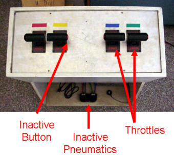
Drive your machine! Each joystick on the podium will supply a maximum positive voltage when it is pushed forwards (towards the low marking on the joystick) and will supply a maximum negative voltage when it is pulled backwards (towards the high marking on the joystick). Supply voltage out of the control box will be a scaled value of the output voltage from the battery. Nominally, this value should be around 9V, which corresponds to the torque-speed data recorded for the Tamiya motors. How your machine responds to positive or negative voltage depends on how you have wired your AMP 14-pin motor connector. Be sure to test your machine before impound day so you can adjust the wiring for the easiest possible operation. You will not be allowed to change this afterward.
The high and low markings, the buttons on the joysticks, and the pneumatic pedals are all non-functional or inactive for this contest.
-
Practice a lot! Remember, driving 2.007 machines is difficult. Plenty of time should be allocated for practice.
Do not leave the control box on the table when you are done or you may lose the right to use it. Return it to the magnet on top of the podium.
Also, do not remove the control box from the area surrounding the table.
Important Note: The control system is designed to run your machines for no more than a couple of minutes. Running your motors for a long period of time will cause things to get very hot. If you see the amber “thermal warning” light go on, you should keep the power plugged and let your box cool for 1 minute. If this happens to you frequently, you might also be slowly frying your motors.


