
(a) Pantano, et al. [1] discuss several previously reported estimates of CNT elastic properties. Explain how the cited works in this review inferred the elastic properties of these CNTs from resonance of the structure (how did they do it, and how does resonance relate quantitatively to E?).
Several different groups have performed experiments to determine elastic properties using vibration and resonance of the CNT structure:
Treacy, et al. (1996) [2] used thermally induced vibration of cantilevered multi-walled nanotubes (MWNTs) in a TEM to determine a value of Young’s modulus. Their technique involved placing MWNTs on the edge of TEM grid. With one end of the MWNT fixed on the edge of the TEM grid, the other end of the MWNT was free to move. Focusing the TEM on the free end of the tube was not possible because the tube was vibrating, due to thermal energy, in-and-out of the TEM focal plane. By measuring the width of the blurred tip, relative to the constrained end, the amplitude of the vibration could be inferred. The temperature of the MWNT was varied and a linear relationship was observed between temperature and mean-squared amplitude of the vibration. The Young’s Modulus was determined from this information.
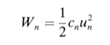
The vibration energy, Wn, is the thermal energy in the system equal to kT, which obeys the Boltzmann distribution, and un is the horizontal vibration amplitude of the tip.
The effective spring constant is given by
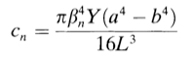
where Y is the Young’s Modulus, L is the tube length, a and b are the outer and inner diameters of the tube respectively, and the β term is related to the vibration mode of the MWNT, which is assumed to be analogous to that of a clamped cantilever. It is given by
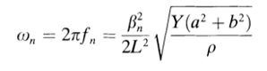
where ρ is the density of the CNT wall material. For CNTs at room temperature a frequency of 100 MHz can be expected. Using the above relations the Young’s Modulus was inferred to be roughly 1.8 TPa on average.
Using the same technique as Treacy, Krishnan, et al. (1998) [3] determined the Young’s modulus to be between 0.9 and 1.7 TPa for a single-walled nanotube (SWNT).
Poncharal, et al. (1999) [4] used a slightly different technique to infer the Young’s modulus. This group mounted MWNTs on a specially designed TEM grid such that they could be biased. A grounded counter electrode was mounted within 20 um of the ends of the MWNTs. The application of a bias to the nanotubes caused a deflection towards to the grounded counterelectrode. By applying a time dependent oscillating voltage to the nanotubes, the resonance frequency could be found. The frequency was evident when large deflections were observed for relatively small voltages. Using essentially the same method and governing equation as in the previous two papers,
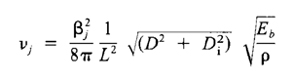
based on the assumption that nanotubes can be modeled as resonantly excited cantilever beams, allowed the calculation of Young’s modulus. Poncharal, et al. confirmed previous measurements of modulus to be roughly 1 TPa.
(b) On p. 795 [1], the authors state that the CNT can be described with three elastic constants, but they also state that the wall material is isotropic. Isotropic materials require only 2 independent elastic constants, so demonstrate in terms of material and crystal symmetry why three are employed.
Two elastic constants are required for materials that are isotropic in space. The reference to the isotropic elastic properties of a two dimensional hexagonal structure as being isotropic indicates isotropy only in its two in-plane dimensions. Consider a graphene sheet: it is isotropic with respect to in-plane stretching and can be described fully with a stretching stiffness C and a Poisson’s ratio v, the two constants we expect for an isotropic material.
The analogy between space isotropy and in-plane isotropy dissolves when we consider applying a load normal to the plane. In a spatially isotropic material, this can be viewed as an in-plane load on a different plane, identical to the first by spatial symmetry. In a two-dimensional sheet, however, an out-of-plane load causes a fundamentally different form of deformation. Consider the example of the graphene sheet: an in-plane load causes bond stretching and rotates bond angles in plane, increasing some and decreasing others. Now, consider a hexagonal junction in the form of a Y loaded out-of-plane: all bond angles are reduced. This unique deformation is governed by a separate elastic constant D, the flexural rigidity.
All three constants are required to describe a nanotube, a rolled graphene sheet. The in-plane or membrane stretching stiffness and the Poisson’s ratio govern the behavior of the nanotube loaded axially, though this stiffness differs from the stiffness of the equivalent, unrolled sheet due to the change in geometry. The flexural rigidity governs the deflection of the nanotube. Unlike in the case of a spatially isotropic materially, it is not possible to describe this behavior in only two constants.
References
[1] Pantano, Antonio, David M. Parks, and Mary C. Boyce. “Mechanics of Deformation of Single- and Multi-wall Carbon Nanotubes.” Journal of the Mechanics and Physics of Solids 52 (April 2004): 789-821.
[2] Treacy, M. M. J., T. W. Ebbesen, and J. M. Gibson. “Exceptionally High Young’s Modulus Observed for Individual Carbon Nanotubes.” Nature 381 (June 20, 1996): 678-680.
[3] Krishnan, A., E. Dujardin, T. W. Ebbesen, P. N. Yianilos, and M. M. Treacy. “Young’s Modulus of Single-walled Nanotubes.” Physical Review B 58 (1998): 14013-14019.
[4] Poncharal, P., Z. L. Wang, D. Ugarte, and W. A. de Heer. “Electrostatic Deflections and Electromechanical Resonances of Carbon Nanotubes.” Science 283 (March 1999): 1513-1516.
Plasticity and fracture of microelectronic thin films/lines Effects of multidimensional defects on III-V semiconductor mechanics Defect nucleation in crystalline metals Role of water in accelerated fracture of fiber optic glass Carbon nanotube mechanics | Problem Set 2 | Problem Set 3 | Problem Set 5 Superelastic and superplastic alloys Mechanical behavior of a virus
Effects of radiation on mechanical behavior of crystalline materials


