
(b) The papers you have chosen discuss the elastic properties of CNTs. Of course, the applications people are excited about are related to the high tensile strength of these organic fibers. We know they’ll easily buckle in compression, and it’s hard to think of apps that would benefit from that. Read the 2 papers cited by Pantano, et al. [1] that discuss nanotube fracture to review this concept.
Then compute the number of carbon bonds that must be broken to achieve tensile fracture of a single CNT (not a multiwall).
Let’s consider the case of a zigzag nanotube, as Belytschko, et al. [2] discuss. In this case, fracture occurs around the circumference, when a circumferential set of bonds aligned axially with the tube are broken. Consider a sheet of graphite, specifically a set of parallel bonds. The equilibrium bond spacing given by Zhang, et al. [3] is 0.1315 nm, and all bond angles are 120 degrees. Simple geometry is sufficient to determine the normal spacing between perpendicular bonds as [0.1315*√(3)] nm, or, generally, [bond length*√(3)]. The circumference of a nanotube of diameter d is simply π*d, and we can divide this by the bond spacing to approximate the number of bonds along (and perpendicular to) the circumference that must be broken.
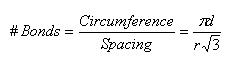
Note that r is the equilibrium bond spacing.
It [elastic energy stored at fracture] should be the number of carbon bonds transversing the fracture plane, multiplied by the carbon-carbon bond strength, but is it?
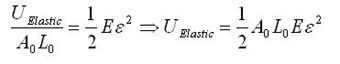
First, consider the general elastic energy stored per unit volume, and the simply transformed total elastic energy stored. (We are implicitly assuming there is no plasticity aside from fracture.)
The modeling values of Belytschko, et al. will be used throughout. For stress purposes, the effective area over which the stress is applied is taken as the circumference of the nanotube multiplied by a value h, a wall thickness, which Belytschko, et al. take to be the interlayer separation of graphite h = 0.34 nm, and which is given as a standard value for this sort of calculation. Morse potential simulations [2] give a failure strain of 15.7%, or a failure stress of 93.5 GPa. For the other constants, E = 1.16 TPa, A0 = circumference*h, L0 = r = 0.1315 nm = equilibrium bond spacing. While the first bond fails before the fracture strain is reached, we will take the failure strain to be the strain at which the first bond breaks, and assume the difference is minimal since no plasticity is expected. Next, consider the number of atomic bonds over which this energy is distributed, given in Eq. 1 for a zigzag nanotube. Once a single bond is broken, fracture follows readily at little additional displacement [2]. The expression simplifies as follows; note that the result does not depend on the nanotube size.
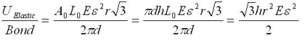
Using the previously given values, the energy applied to each bond at fracture strain is 0.91 eV; the dissociation energy for a single bond is given as 5.62 eV [2]. Though this is within the expected order of magnitude, fracture is observed at a significantly lower energy investment than calculated, and Belytschko, et al. note that fracture has been observed experimentally at stresses significantly lower than even these simulations. It is worthy of mention that in the simulations of Belytschko, et al. one bond was weakened by 10%, guaranteeing the site of fracture nucleation, but this is not at all sufficient to explain this discrepancy. Using the Brenner rather than the Morse results in [2] gives a result of 2.89 eV per atom, which is still significantly off.
These results can be extended to armchair or chiral nanotubes by appropriate modification of the function giving the number of bonds broken; Zhang, et al. [3] show in Fig. 6 that fracture proceeds by the stretching and breaking of axial or semi-axial bonds, rotating the fracture surface about an axis normal to the tube such that it becomes angular/ellipsoidal.
References
[1] Pantano, Antonio, David M. Parks, and Mary C. Boyce. “Mechanics of Deformation of Single- and Multi-wall Carbon Nanotubes.” Journal of the Mechanics and Physics of Solids 52 (April 2004): 789-821.
[2] Belytschko, T., S. P. Xiao, G. C. Schatz, and R. S. Ruoff. “Atomistic Simulations of Nanotube Fracture.” Physical Review B 65 (2002): 235430.
[3] Zhang, P., Y. Huang, H. Gao, and K. C. Hwang. “Fracture Nucleation in Single-Wall Carbon Nanotubes Under Tension: A Continuum Analysis Incorporating Interatomic Potentials.” Transactions of the ASME 69 (2002): 454-458.
Plasticity and fracture of microelectronic thin films/lines
Effects of multidimensional defects on III-V semiconductor mechanics
Defect nucleation in crystalline metals
Role of water in accelerated fracture of fiber optic glass
Carbon nanotube mechanics | Problem Set 2 | Problem Set 3 | Problem Set 5
Superelastic and superplastic alloys
Mechanical behavior of a virus
Effects of radiation on mechanical behavior of crystalline materials


