
(a) What is the average Young’s elastic modulus of the Au nanopillar in Fig. 1A of Li [1]? From comparison of these data with E of Au reported in the literature, do you infer that elastic properties of Au are size-dependent down to these sample diameters?
The average Young’s elastic modulus of the Au nanopillar is the slope of the unloading curve which is equal to 48.5 GPa. The E of Au reported in literature is around 43 GPa along the direction which is the same direction in which the compression was done on the Au nanopillar. We conclude that the elastic modulus is not dependent on specimen size as it is a property that is related to the internal energy change associated with bond stretching or compression and thus does not depend on the size of the sample.
(b) Derive the expression used several times by Li [1] relating the maximum shear stress generated within an indented material as a function of applied load, Young’s elastic modulus, and indenter radius. You may wish to consult K. Johnson’s Contact Mechanics [2].
We are interested in modeling the maximum shear stress a material experiences when being indented. This is done by considering the elastic contact of two smooth surfaces. Among other things, we need to know how contact area changes with increased applied load. Contact mechanics allows us to do this so that we can also predict the deformation (stress, strain) in the region of the material affected by the contact.
We begin by describing the geometry of two surfaces being brought into contact. This allows us to define our problem in terms of critical variables.
Consider 2 surfaces in contact described by Eq. 1 and Eq. 2 below. Here, we assume that we have two smooth surfaces with surfaces which can be described by an equation which must be continuous up to the second derivative.
| Surface 1: |
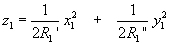
|
Eq. 1 |
| Surface 2: |
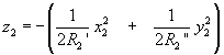
|
Eq. 2 |
Therefore, the separation is h = z1 - z2. However, this separation currently requires two different coordinate systems for its definition.
Switching to common set of axes: x and y
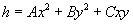
|
Eq. 3 |
Since these axes are arbitrary, we can pick them intelligently to make our description of the problem easier. Here, we choose our axes such that C = 0,
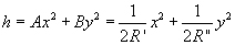
|
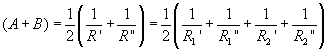
Eq. 4 |
where A and B are positive constant; R’ and R" are the principal relative radii of curvature.
We can get relations for A and B using geometrical considerations. This is done in Appendix 2 of [2], but omitted here for clarity.
|
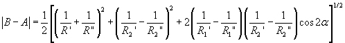
Eq. 5 |
|
Eq. 6 |
where α is the angle between the axes of principal curvature of each surface (x1 and x2)
We will now consider two surfaces of general shape, centered at O, deformed with a normal load P applied (Figure 1).
Image removed due to copyright restrictions. Please see Fig. 4.2 in [2].
Figure 1 Schematic showing the geometry of the problem [2].
We now must utilize Hertzian contact theory to determine displacements, which then allow us to find strains and stresses. Hertzian theory makes some assumptions which must be declared at this juncture. It is assumed that each body can be regarded as an elastic half-space which is loaded over an elliptical area on its surface plane. This is done because well-developed solutions exist for solving boundary value problems for an elastic half-space. It is also assumed that the surfaces are continuous and non-conforming. The strains experienced by the half-space area small. These last two considerations are represented by the assumptions that the contact radius is much smaller than the radius of curvature of each body. Finally, it is assumed that the surfaces are frictionless.
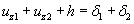
During compression, distant points T1 and T2 move towards O by displacements δ1 and δ2.
Due to contact pressure, the surface of each body is displaced parallel to O in the z direction by uz1 and uz2 relative to T1 and T2.
Looking at points S1 and S2, which are coincident within the elastic surface:
|
Eq. 7 |
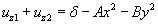
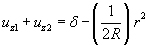
If we write δ = δ1 + δ2 and use Eq. 6, we get elastic displacements:
|
Eq. 8 |
At this point, we can consider the specific geometry of our problem of interest to simplify the equations which describe the evolutions of the contacting bodies.
For this situation, we are interested in the contact of two solids of revolution. A solid of revolution is a solid body which is obtained by revolving a plane figure about some axis.
(R1’ = R1" = R1 ; R2’ = R2" = R2)
Therefore: A = B = ½(1/R1 + 1/R2)
The circular symmetry of the problem means that the contact area will be circular (with a radius we will call a).
|
Eq. 9 |
Where (1/R) = (1/R1 + 1/R2) is the relative curvature.
A pressure distribution which gives displacements satisfying Eq. 9 is given in Johnson Section 3.4 [2]. This gives the stress resulting from an applied pressure over a circular area for an elastic half-space (Hertzian contact).
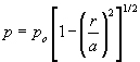
|
Eq. 10 |
This pressure distribution gives the displacement:
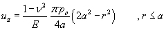
|
Eq. 11 |
Since the pressure acting on the second body is equal to the first, we can write:
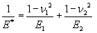
|
Eq. 12 |
Substituting Eq. 11 into Eq. 9 for uz1 and uz2, we are left with:
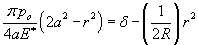
|
Eq. 13 |
Which give us the radius of circle contact, a, and the mutual approach of distant points, δ:

|
Eq. 14 |

|
Eq. 15 |
The total load compressing the solids is:

|
Eq. 16 |
Substituting this into Eq. 14 and Eq. 15, we get:

|
Eq. 17 |
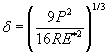
|
Eq. 18 |
We also get an equation for the maximum pressure, po, if we compare our new expressions for a and δ with the old ones.
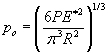
|
Eq. 19 |
We now have expressions for contact size, compression, and maximum pressure.
For this pressure distribution, the stresses beneath the surface along the z-axis are (refer to Johnson Section 3.4 [2]):
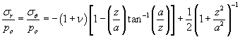
|
Eq. 20 |
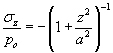
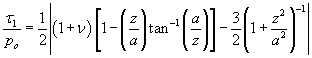
|
Eq. 21 |
These are the principal stresses. Therefore, our principal shear stress is:

|
Eq. 22 |
We now plug in the values for our principal stresses to get an expression for the maximum shear.
|
Eq. 23 |
This principal shear stress is maximized at a depth of z = 0.48 a (for ν = 0.3). This step was evaluated in Maple. Substitution gives us an expression for the maximum shear stress under an indenter.
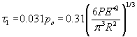
|
Eq. 24 |
P is the indentation load. R is the radius of curvature of the indenter tip. E* is the effective elastic modulus.
This equation tells us that the maximum shear stress occurs below the contact surface and is equal to 0.31 times the maximum pressure. This can also be expressed in terms of variables which can be easily measured in an experimental situation. From this equation, we would expect critical plastic events to occur underneath the surface of an indented material.
References
[1] Li, Ju. “The Mechanics and Physics of Defect Nucleation.” MRS Bulletin 32 (February 2007): 151-159.
[2] Johnson, K. L. Contact Mechanics. Cambridge, UK: Cambridge University Press, 2008. ISBN: 9780521347969.
Plasticity and fracture of microelectronic thin films/lines
Effects of multidimensional defects on III-V semiconductor mechanics
Defect nucleation in crystalline metals | Problem Set 2 | Problem Set 3 | Problem Set 5
Role of water in accelerated fracture of fiber optic glass
Carbon nanotube mechanics
Superelastic and superplastic alloys
Mechanical behavior of a virus
Effects of radiation on mechanical behavior of crystalline materials


