
(b) The papers you have selected study the onset of plasticity via the applied contact load of indentation. Explain and illustrate why the location of homogeneous dislocation nucleation under an indenter is expected to occur below the indented material free surface, rather than at the indenter/material interface.
The homogeneous dislocation nucleation occurs at the maximal shear stress state position. In the nano-indentation experiment in our papers, the stress field generated by an indenter can be calculated and the maximum shear stress position is the place where the homogeneous dislocation nucleation takes place. In problem set 2, we calculated the stress beneath the indented surface along z-axis (depth) in 3-D case. Based on problem set 2, we know that the principal shear stress is

|
Eq. 1 |
where σz and σθ are principal stresses expressed as
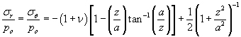
|
Eq. 2 |
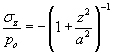
|
Eq. 3 |
Here p0 is the maximum pressure, 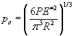
Therefore
 =
=
= 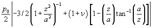
|
Eq. 4 |
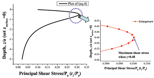
I plotted the (eq. 4) by using Excel and Origin Pro 7.0 (Here I assumed v = 0.3 and set a = 1) and the resulting graph is presented below. Now we see that the maximum shear stress state is inside the indented materials not the interface. In 3-D case plot, the maximum depth is z/a = 0.48.
Therefore we can say that homogeneous dislocation nucleation under an indenter is expected to occur below the indented material free surface, rather than at the indenter/material interface. Also, we can learn that nano-indentation experiments probe the bulk property, not the surface property of the material.
Another illustration is possible. The nano-indentation experiments can be thought of such that the indenter tip works somewhat like a lens, projecting the applied force to focus the maxima shear stress to an internal point inside the sample, away from the surface. [1]
In 2-D case, the plotting equation can be different from 3-D and this calculation is done at problem (c). Also we found an experimental report about the 2-D case. In that case the maximum shear stress position is z/a = 0.78. [2]
Image removed due to copyright restrictions. Please see Fig. 1 in [2].
(c) Derive the location of maximum shear stress (i.e., depth) for indentation with a Hertzian elastic sphere for the case of 2-D indentation (i.e., the sphere is really a cylinder). Johnson’s Contact Mechanics [3] and the PRB (2003) [4] and its cited papers are good references.
Handwritten Solutions (PDF)
Supplemental Calculations
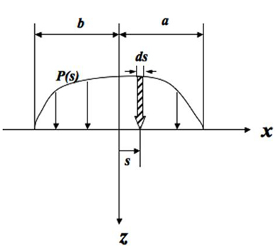
1. Dummy variable s in equation (b)
As can be seen in the below figure, when a pressure distribution is applied on a xy plane, at x=s point, x is shifted by amount of s, thus x is replaced by (x-s). Then the pressure applied at x=s point is written as p(s) instead of p(x).
In this 2-D indentation case with same radius R(= R1 = R2), a = b.
2. The distribution of pressure
When a function takes the form below,
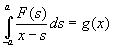
the solution F(x) has this form.
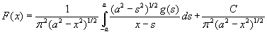
where 
Thus 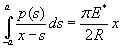 (equation (c)) has a solution p(x) as seen in equation (d).
3. Procedure from the step (h) to the final answer
When we take derivative of 1 with respect to z,
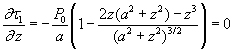
Thus,
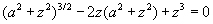
When we calculate this through a calculator, we can get z = 0.78a, and there τmax = 0.30 p0
(d) Minor, et al. [5] show interesting experiments that enable visualization of dislocations in a thin foil of Al during indentation, similar in goal to the MD simulations of Al discussed in your other two papers [1, 4]. Discuss how well the authors justified the assumption that the load-drops in the load-displacement data correspond to homogeneous dislocation nucleation, as opposed to heterogeneous dislocation nucleation from grain boundaries or motion of pre-existing dislocations. This analysis should include consideration of images, reported data, and expected values of required stresses, dislocation spacing, and sufficient “perfect crystal” size comparable to the elastic strain field of an indenter.
Minor, et al. [5] claim that the load drops in their nanoindentation data correspond to the homogeneous nucleation of dislocations within the crystal. In determining this, it is important to consider the possibility that these load jumps could be caused by heterogeneous dislocation nucleation from grain boundaries or the movement of pre-existing dislocations.
First, we consider the possibility of dislocations nucleated from grain boundaries. From inspection of the TEM images in Fig. 2 (and the corresponding movie in the online Supplemental section), we can see dislocations originating in the interior of the grain, underneath the indenter. This is most easily seen in the later parts of the movie (closer to load drop 3), where an increased amount of dislocation activity can be seen in this region. The possibility of grain boundary nucleated dislocations can also be ruled out by considering the size of the grain used to model a perfect crystal with the elastic stress field under the indenter. Our previous analysis (work done in PSet 2b and PSet 3c) has shown that the shear stress drops significantly and becomes close to zero at distances of greater than three contact radii away from the contact point. By looking at Supplementary Image 2 [5], we can see that the contact radius is approximately 37.5 nm while the grain boundaries are hundreds of nanometers away from the contact point. Since these boundaries are all more than five times the contact radius away, the shear stress acting on the boundaries will be insignificant. Since a large stress must be concentrated on a grain boundary for a dislocation to be emitted, this possibility can be ruled out. This combination of visual evidence and consideration of the applied stress field show that grain boundary nucleation cannot explain the load drops in the nanoindentation data.
Next, we look at the possibility of the load drops corresponding to critical events involving the movement of preexisting dislocations. The images of the 1st load drop show that this cannot be the case here, where a dislocation-free crystal becomes filled with dislocation debris. Images of the 2nd load drop show a greatly increased dislocation density, pointing to the fact that dislocation nucleation is occurring. Finally, as mentioned earlier, a higher level of dislocation nucleation and movement can be observed under the indenter contact when compared to the rest of the crystal at the 3rd load drop. The possibility of existing dislocation movement can also be analytically considered by looking at the stress necessary to move dislocations through an existing dislocation structure. The existing dislocation density in Fig. 2e is estimated in the article as ρ ~ 1014 m-2. Using the Taylor work hardening law (shown below), we can estimate the shear stress needed to cause slip in a crystal with a given dislocation density. This theory is based on the stress needed to pull two dislocations past each other. Here, the spacing between dislocations, l, is equivalent to the inverse square root of the dislocation density, ρ. By choosing α to be unity (the high end of the usual 0.05 to 1 range) and using material properties for aluminum (G = 25 GPa; b = 0.286 nm), we can calculate that a shear stress of 71.5 MPa would correspond this mechanism. Since the slip event occurs at a much higher stress than this, the motion of existing dislocations moving through an existing dislocation network cannot be the mechanism responsible for the load drop.

|
Eq. 1 |
The TEM images and a calculation of stress under the indenter points to the fact that homogeneous dislocation nucleation is occurring, corresponding to the load drops in the indentation data. The dislocation events can be observed to occur at a position underneath the contact surface in a region where elastic contact theory predicts the shear stress will be highest. The magnitude of shear stress in this region is of the same order (~2 GPa) as that predicted to be necessary to nucleate a dislocation in a dislocation-free aluminum crystal [6, 7].
Image removed due to copyright restrictions. Please see Supplementary Fig. 2 in [5]. (PDF)
References
[1] Li, Ju. “The Mechanics and Physics of Defect Nucleation.” MRS Bulletin 32 (2007): 151-159.
[2] Gouldstone, Andrew, Krystyn J. Van Vliet, and Subra Suresh. “Simulation of Defect Nucleation in a Crystal.” Nature 411 (June 2001): 656.
[3] Johnson, K. L. Contact Mechanics. Cambridge, UK: Cambridge University Press, 2008. ISBN: 9780521347969.
[4] Van Vliet, Krystyn J., et al. “Quantifying the Early Stage of Plasticity Through Nanoscale Experiments and Simulations.” Physical Review B 67 (2003): 104105.
[5] Minor, A. M., et al. “A New View of the Onset of Plasticity During the Nanoindentation of Aluminum.” Nature Materials 5 (2006): 697-702.
[6] Gouldstone, A., H. J. Koh, K. Y. Zeng, A. E.Giannakopoulos, and S. Suresh. “Discrete and Continuous Deformation During Nanoindentation of Thin Films.” Acta Materalia 48 (2000): 2277-2295.
[7] Kramer, D. E., K. B. Yoder, and W. W. Gerberich. “Surface Constrained Plasticity: Oxide Rupture and the Yield Point Process.” Philosophical Magazine A 81 (2001): 2033-2058.
Plasticity and fracture of microelectronic thin films/lines
Effects of multidimensional defects on III-V semiconductor mechanics
Defect nucleation in crystalline metals | Problem Set 2 | Problem Set 3 | Problem Set 5
Role of water in accelerated fracture of fiber optic glass
Carbon nanotube mechanics
Superelastic and superplastic alloys
Mechanical behavior of a virus
Effects of radiation on mechanical behavior of crystalline materials


