
Cloth Patch for Monitoring Contractions!
by Karina Isaak
Hey guys,
I found a pressure sensor matrix that we could adapt to a pressure sensor patch on the stomach of the women in labor on this webpage (see below). It gives instructions how to build a pressure sensor by using two pieces of cloth and conductive thread! If I understand it right, you just have to sew everything together in the explained way and connect it with external pull-up resistors! They even provide the Arduino code. Click through the pictures on the top, all steps are explained in detail and a video is provided in which you can see how it works.
http://www.instructables.com/id/Pressure-Sensor-Matrix/
We should try this! Maybe we can make it as a sticky patch.
What do you think?
Home Stretch
by Grace Yao
It’s crunch time now! MIT Museum 1-minute pitches this Saturday, and 15-minute presentations in class next week.
We’ve finally chosen a team name: Team Partayuda, from the Spanish words for “birth” and “help.” So here’s what’s up, as far as I know…
Maysun is working on the breadboard and programming for the pressure sensor - a capacitor, with rubber in the middle, and [AB] is going to make it. We tried making the EMG last week, but it did not work out.
Karina found the cool conductive thread project that she just posted, so she and [LT] are going to try to make that happen; [LT] is also working on Arduino code for the button.
So in total we should have 3 different ways of input to test (which may or may not happen before class presentations): the capacitor, the conductive thread, and the button…I think right now the button is the closest to being finished.
I’m going to work on the processing code to take the input and provide an output of the results we want to show. However, we don’t have the monitor yet, so this may end up just being displayed on a computer. [AB] and I are going to put together the poster, including the problem statement, our solution, Pugh chart, Design Compass, and design specs among other things, while [LT] is going to make a slide for the museum pitch.
Busy week, but we’re almost there!
Response From Nicaragua
by [LT]
Hi All,
Our contacts in Nicaragua have kindly responded to our questions with very interesting information that has really defined our problem. See their responses below.
- The women know about when to arrive at the hospital. They receive information when they receive their prenatal checkup. Births can happen during transport due to the distances involved. Women don’t have ready access to an OB/Gyn and subsequently need to travel up to 4 hours to receive specialized attention.
- The monitoring is crucial in knowing the condition of the mother and the fetus.
- We use a medical method in which we place a hand over the patient’s abdomen for 10 minutes and perceive the contractions. We have immense difficulties because of the large number of patients. There are only 2 doctors per shift for 15-25 patients which need to be monitored every 4 hours and apart from that, we need to attend to births and do cesareans and fill out a stressful amount of paperwork. On occasion, we don’t manage to monitor all the patients and are limited to just asking if they have had pains and with what frequency. To listen to the fetal heart rate, we use a stethoscope. Often, we don’t listen to it because we have to move them around to listen to it with a fixed ultrasound which takes up more time.
- To give you an idea of how difficult it is to monitor all the patients, before every shift, we pray to God that [the room] is not too full.
- To see if it would cause the mother stress, it would be necessary to conduct a study, and that depends on various factors, but for us it would be very valuable information.
- Don’t know if it will be effective or not. For that, we’d have to try it, but I think that for the level of education, it would be better that they didn’t participate (I think he means that due to their lack of education, they wouldn’t do it right- they shouldn’t have control of the input of the monitor).
- Contraction control is crucial. We do it every four hours when the expectant mother doesn’t have any labor problems and each hour when she is in labor. This last case we control the labor through the partogram.
Instructable
by Grace Yao
I think the Processing code this girl wrote could be helpful to us right now (although our pulse ox code might already do the trick for now); the entire Instructable might be useful in the long run for future work.
http://www.instructables.com/id/Fabric-bend-sensor/
“Using conductive thread, Velostat and neoprene, sew your own fabric bend sensor.
This bend sensor actually reacts (decreases in resistance) to pressure, not specifically to bend. But because it is sandwiched between two layers of neoprene (rather sturdy fabric), pressure is exerted while bending, thus allowing one to measure bend (angle) via pressure. Make sense? Watch below:”
By the way, our team name is now Babytrakr!
Pennies for Your Muscles
by Maysun M. Hasan
Hey,
So I totally suck at blogging!!! I have a lot to say about the progress of our device that has happened in the last week. The last time I wrote, I had a plan for the EMG and I was about to build. Well I built it and realized that this was not the best way to do it… This is the schematics for it anyways.
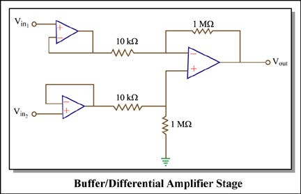
Image by MIT OpenCourseWare. Adapted from circuit designed by Ankit Gordhandas, Irena Hwang, and Vinay Ramasesh.
This is the differential amplifier stage I described earlier. I built it, along with super cheap, super cool electrodes :) (See below)
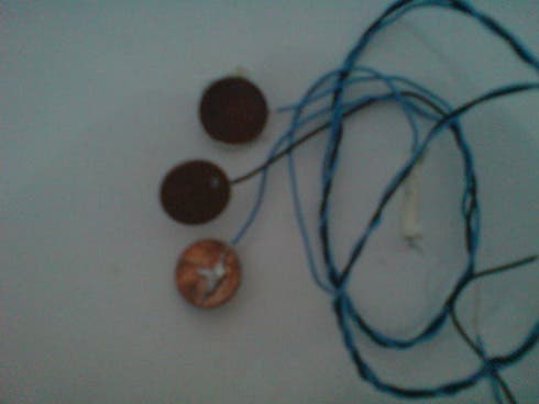
Pennies as electrodes
Yes… they are pennies that I soldered to wires… but they work so whatever. So I build the circuit with LM741’s (the most typical op amp you can get)…and… it didn’t work. I know it was able to take the difference between two signal… but not muscle signals. So I did some research and found out that because it is such a tiny signal… and better op amp is necessary. So I used LT1637’s for the buffer and a LM358 as my amplifier. And… it didn’t work. After debugging though… I found my signal… But!!! It was tiny and very noisy!!! Also it was not the same shape as we thought it would be. It marked when the muscle started to contract, but not the whole contraction. This signal was so inconsistent that I felt it would not be the best for our prototype. That is why EMG was out… but what now… we have no input… Well this is where the capacitor idea that is mentioned in a few of the blog entries comes in. Sorry for the weird timeline… I am horrible at posting.
Convo with Dr. Acker
by [AB]
Thanks Mays for reminding me to post also! Sorry this is very late and happened 2 weeks ago but here’s how the conversation with Dr. David Acker from Brigham and Women’s Hospital went:
- What do you use to measure contraction?
- he measures the frequency, duration, and intensity of each contraction
There are 3 subjective ways to measure:
- ask woman how much it hurts and to record frequency of contractions on paper
- place monitor on abdomen and when contraction causes stomach to rise the pressure sensitive device will monitor by graphing on a slowly moving strip of paper (can’t record the intensity of the contraction with this device, however.)
- membrane ruptured and tubing placed through vagina into uterine cavity—intra-amniotic pressure measured and this is the most precise way to measure contractions but it’s invasive and uncommonly used
- How does the tocodynamometer work?
- Measures contraction rise by pressure sensitive sensor (device is like a piston)
- When do you know baby is coming?
- Contractions occur every 5 minutes lasting 1 minute each for the past hour, then the baby is going to come soon
- There is monitoring of the woman even a week before the baby comes
- Labor is not defined by the contraction rate, it is defined by the contractions leading to a cervical change (that’s where the partogram comes in)
- Rock hard cervix until contractions loosen it for opening
- Fetal heart rate response indicates complications (our device will notify the doctor when the contraction ends so he can check the fetal heart rate, it will not have a fetal heart rate monitor…yet?)
- On average, the fetal heart rate shouldn’t change, but when fetal heart rate increases → reassuring because indicates an acid/base balance
- When fetal heart rate decreases → various patterns so doctor needs to determine which pattern happens to see what is wrong
- What smarts are the best out of EMG, flexiforce or push button?
- In the US, Dr. Acker doesn’t believe a push button will be effective because we’re simply replacing a pen and pencil for the women to a ball. However, he thinks it might help if they are in lots of pain and don’t wish to record their contractions.
- He thinks the rubber pressure sensor is a very cool idea, however, the abdominal muscle or rather skin on top of the abdomen doesn’t harden so the pressure sensor should be something that notes rises in abdomen (~1 cm rise, Maysun’s mom also said the same thing)
- Women’s abdomens are different so an external sensor needs to accommodate these variations
- Thickness of abdominal wall also varies
We took all these answers into consideration when brainstorming for our prototype two weeks ago. As you can see in the post below, our prototype changed numerous times because we wanted to accommodate all the ideas and comments from doctors in Nicaragua and the US. Ultimately, we went for a pressure sensor that is different from a toco, but still measures abdominal rise for contraction rate to correlate to a hand squeeze ball. Dr. Acker also agreed to let us see his operation room if we needed some more ideas, so if the project continues we have access to his resources. He was very nice about answering questions and very interested in helping out in the future.
Radio Awesomeness
by Maysun M. Hasan
Ok, it’s me again,
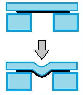
So, last time I told about the EMG circuit, which we rejected from our prototype because the signal was not what we expected and it was way too small and noise. I was reading up on other ways to do determine contractions (this was about 2-3 weeks ago), and discovered that EMG is not common method to detect contractions, even in the use. This is because there is also of other muscle interference, like fetal heart beat, maternal heartbeat, and maternal body movement artifacts. There is some cool research into additive filtering, and also how EMG’s are better in detecting when the baby is going to be delivered, but this research is not even applied here in the US, and what doctors need now is something that works. That is why we switched focus to a tocodynamometer, toco for short. This is basically a pressure sensor on the stomach that detects the upward movement of the uterus during contraction:

Courtesy Hesperian Foundation. Used with permission. From Werner, David, Carol Thuman, and Jane Maxwell. Where There Is No Doctor: A Village Health Care Handbook. Berkeley, CA: Hesperian Foundation, 2010, pp. 258. ISBN: 9780942364156.
We have been told that during a contraction, the uterus stiffens and moves about 1cm up. This is where the Toco comes in. It measures the pressure exerted by this upward force. After a long brainstorming section, we decided that a cool why to make a cheap and use to manufacture sensor was to make a capacitor. For a parallel plate capacitor, the equation is:
C= ϵ0 ϵr A/D
so as you squeeze the plates together, the capacitance changes, and all you need for the sensor are 2 conductive plates, which is locally available!!! I thought it was brilliant. To measure the difference in capacitance, I was going to make a simple LC oscillator, and have the sensor is parallel with the oscillator C. Thus, as the plates are squeezed together, the frequency of the oscillator changes, and we can plot the frequency changes over time. Here is the oscillator, the antenna in the picture is our sensor:
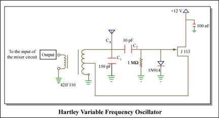
Image by MIT OpenCourseWare. Adapted from Ron Roscoe’s 6.102 Introductory RF Design Laboratory, Laboratory No. 4, Spring 2008.
I figured that there was about 10 pF variable capacitance, so in order to get a good frequency range, I was going to have two oscillators and mixer them and filter out all the frequencies I didn’t want:
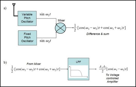
Circuit design to filter unwanted frequencies
I know, a little technical… but it needs to be documented.
The mixer is below:
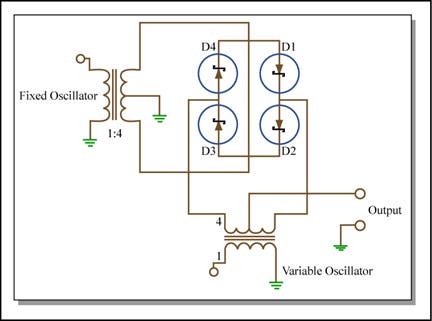
Image by MIT OpenCourseWare
Now!!! The really cool part of this is that these are all parts of a radio!!! A radio is cheap and there are already tons of mechanics who know how to work/fix them. The infrastructure exists and it would be easy to implement anywhere. I was so amazed with myself, I was telling a friend while debugging my circuit, and that’s when Velostat came into the picture. My friend saw what I wanted to do, told a much simpler and cheaper way to do this. So this eliminates our second prototype. Next time, Velostat and how it works!!!
Logo
by Grace Yao
_
_
Team name in baby blue block letters next to baby’s footprints.
Karina and Nathan put together this logo last week for our poster - isn’t it cute?! Sort of makes the whole project feel more legitimate to me (not that it didn’t before, but having some sort of branding helps).
Alien Mind Control!!!
by Maysun M. Hasan
Hi guys,
I feel I need to write this blog entry before the end of the term. So we decided at the end to use Velostat, a material I found through a friend, as our pressure sensor. So the technical description that 3M, the manufacturer of the material, provides is an “opaque, volume-conductive, carbon-impregnated polyolefin. Easily grounded, the electrical characteristics are not affected by age or humidity, and are suited for handling, shipping and storage.” I found this material at a site called lessemf.com, a site that, hilariously enough, specializes in materials to prevent alien abduction. Velostat is used to make into helmets to prevent alien mind control. But the real use is basically, it is the material used sometimes as anti-static bags for electrics. Electronics are packed in this stuff and often trashed afterwards.
It costs about $2 for a 1’x3’ piece. Now, what is Velostat? Basically, it is a material that changes resistance as you deform it, and it can be deformed by pressure, or bend. The resistance of the material untouched is about 28 K ohm, but as you bend or apply pressure to it drops. I hooked about a sq. inch of this up to a simple resister to make a voltage divider, high pass filtered it with a capacitor and resister, and voila, a very cheap pressure sensor.
Now working with it, I did find some problems. There is actually no stable baseline, but that’s where the high-pass filter helps. The problem is there is a definite limit to the filter, since our actual signal is very low frequency. But, this is not a big concern after filtering since we can threshold the sensor in the Arduino. Our second problem was that Velostat seems to be sensitive to heat and to sweat. Now this is a huge problem in our application. Fortunately, a piece of scotch tape around the material seemed to help. Lastly, since it is a flexible thin material, there is no easy way to attach wires to the material so there is often lose material. A cool thing, that a lady during our presentation at the MIT museum mentioned was that we could use conductive tape, like copper tape, but this adds cost.
To display the waveform the pressure sensor picked up, I used this code to make a simple oscilloscope with an Arduino (http://accrochages.drone.ws/en/node/90). With this display, I tested out different methods of arranging the Velostat to make it work better. First, I tried bending the material like this:
Arrangement of Velostat during testing.
Then I tried double layering it so to increase reaction. Both methods worked but doubling the layers was more sensitive.
So, after many iterations of the designing the input… ball, to EMG, to Capacitor, we finally reach Velostat. More stuff needs to be looked into, but it is definitely cool.
I would just like to give special thanks to [anonymous MIT student EZ]. I basically forced him to give me some Velostat to experiment with and graciously helped me to make the sensor work optimally.
Presentation at MIT Museum
by Grace Yao
A couple of action shots from the museum presentations last week!
More Action Shots PLUS Interested Physician from Brazil!
by [AB]
You probably can’t read the business card very well because the shot was taken from my iPhone® but Directora Terza Cristina Melo de Brito Carvalho is very interested in our prototype. She works at the Universidade de Sao Paulo and I’m going to e-mail her a copy of our poster. We should keep in contact with her and others interested for the future when we start making more prototypes. The last two pictures are from the EMG testing, and the few minutes that it worked before we realized it wasn’t grounded properly on grace’s arm. The rest are from the poster session (one with Amit’s daughter testing it out), and a picture of the actual poster. I can also upload a file version of the poster soon. Enjoy the pics!


