
A breath-actuated, dosage-monitoring attachment for jet nebulizers to treat multiple patients for respiratory illnesses
Team: Caroline Hane-Weijman, Shan Tie, Mary Jue Xu, and anonymous MIT student [GK]
This content is presented courtesy of the students and used with permission.
- Ideas Right Now
- Problem and Background Information Gathering
- Broken Nebulizer in Nicaragua
- Sites and AeroEclipse
- Background discussion on the Capnography technology
- Background on Vibrating Mesh technology
- Ultrasound Nebulizer Background
- Design Update: Playing with Nebulizer Reservoir
- Background on anti-static coating for the reservoir surface to minimize aerosol particle coagulation
- Pictures of our Reservoir Prototyping Round 1
- One-Way Valves
- Preliminary vapor quantity testing
- Vapor Sensor: Physical setup
- Photos of Testing
- Prototyping and Testing
- General Project Overview & Ryan Assistance
- D-Lab Showcase!
- Vapor quantity testing part 2
- Mini Update
by Mary Jue Xu
Our blog begins! Many things have happened over the past few weeks, including speaking to many experts at Children’s Hospital in Boston. (We will post noted from that shortly. In summary, there are three large areas of focus for improving the nebulizer: dosage, interface, and sterilization. We decided to focus on dosage.
Initially, we started off with the idea of capnography, in which we would measure CO2 exhaled to correlate to dosage intake. The design would have to incorporate the fact that CO2 does not directly link to the dosage. For example, maybe the nebulizer outlet is far from the mouth or the patient breaths out too fast. Also, a physician at the Children’s Hospital informed us that a baby’s exhale was not enough to be measured with capnography.
So, it was back to the drawing boards. Right now, we are focused upon an attachment to the current compressed air nebulizers that will allow 1) dosage to be monitored and 2) multiple patients to use it. So off the end of the nebulizer motor, image a the medicine being pumped into a reservoir that stores the vapors. Then several outlets would lead to the individual patient’s interface. The interface would only open or release vapors under the direction of the patient. Maybe this is by a mechanical sensor that needs to sit on the face or maybe this is a one way valve that is breath mediated so that only with the baby’s breath will the vapors be released from the reservoir. Moving on past this part of the interface is a sensor (likely an LED sensor) that can detect and sum up the amount (volume/time possibly) that passes by and will sum up the volume or time and signal when the full dosage has been given. Jose also had the idea to use some kind of sticker on the face that is color changing after receiving a particular dose.
Problem and Background Information Gathering
by Caroline Hane-Weijman
Just to give some background to our problem and some of the important information we are working with!
Problem Scope
The inspiration for this project came after having visited multiple hospitals, clinics, and health posts in Nicaragua. Currently, the nebulizer is commonly used in developing countries due to the high incidents of respiratory related diseases and infections (the mist from the nebulizer helps unclog liquids found in a sick patient rather than an inhaler). The current nebulizers that are used are air compressors powered by electricity, and the drug most commonly used is albuterol as it is the cheapest. These nebulizers are originally intended for home use but are used for over 30 patients/day in clinics and hospitals, Mothers stand in line with their child until it is their turn to use the nebulizer. These nebulizers do not provide a method for measuring adequate dosage and thus delivery efficacy of the drug to young patients are low, specifically infants. Infants are non-compliant to the face mask that helps administer the drug and the nozzle is just held underneath the infants’ nose without ensuring delivery and wasting a lot of medicine. Additionally, the devices do not have a system to visibly indicate that the device is sterile and ready for use for the next patient, and many are not properly sterilized.
Background
We therefore proceeded to finding more information from experts at Children’s Hospital; including a pulmonologist, respiratory therapist, and a nurse. Below are some important and interesting findings we were able to gather from all three:
Nebulizer Dosage
- Determined dosage for children
- Ongoing discussion amongst doctors
- “Dosage should be same” for a child and adult because more is assumed to be wasted for the child
- Current dosage is 2.5 mL of premixed albuterol dosage; 0.5 mL parts albuterol and 3 mL of saline
- Takes around 15 minutes to administer
- Crying isn’t necessarily bad- children inhale more deeply while crying
- The way to detect inhaled dosage is through
- a deposition tracer; using a gamma camera- something that would emit radiation- sensitive photon emitter.
- Image of the lung to measure how much goes to the lung
- Ventilation profusion scan
- Size of dosage particles are very important
- Too small particles are not helpful and too large will get stuck in upper part of the mouth and not be inhaled
- Diseases cause under ventilation in areas of your body so medicine cannot be ensured to get into all areas of your body that it may need to- also why size matters a lot
- Expense of the machine often correlated to how appropriate the size of the particles are
- Depending on the disease, would ideally like to be able to alter the particle size
- If sealed mask and if humans breath at a rate faster than the nebulizer administers dosage- can assume 100% is being received
Interface
- Important to allow inhalation through mouth and nose
- Especially as many children are sick or crying while they are using it so nose is probably stuffed a large percentage of the time
- Hard to nebulize through mouth while with pacifier
- Don’t like to use mask; sometimes put it by their face while sleeping but they are not getting full medication
- Flavors that would taste could help
- “Bubble masks” in the shape of fish are currently widely used - figures help compliance. The ventilation holes for this mask is located at the bottom which avoids the eyes being too exposed to the medicine
- Mouthpiece for inhaler is used for 5-6 year-olds and older; mask is used for children under 5 years of age
- Play therapy is the most effective way of getting a child to comply (role playing on others and yourself to the child more comfortable with the idea)
Type of Medicines
- Steroids (more expensive)
- Albuterol
- Creates side effects like increased heart rate
- Physical changes occur but difficult to use as a way to monitor since reactions are specific to patient
- Considered a safe medicine
Ideas for monitoring airflow as a way to monitor dosage
- Capnography- summing airflow idea
- Intubation (exist as a color indicator)
- Aerochamber- Meter dose inhalers/ spacers- they have whistles- at proper speed
- Video game of trying to stay ball up in the air
- Balls stay up- to expand lungs- incentive spirometer
Sterilization
- Cold chemical sterilization
- Autoclave- would melt the plastic-some plastics are resistant
- Anything that touches the patient and anything with a backflow (no retrograde flow) should be sterilized
- Tube that touches compressor does not need sterilization, only the cup needs sterilization
- Here, mothers will put parts in a breast milk bag, fill with some water and place it in the microwave
- For multiple patient use: wash with soap and water then boil
- Ball that would expand and compress depending on heat to indicate sterilization? Color changing indicator?
Three major types of Nebulizers
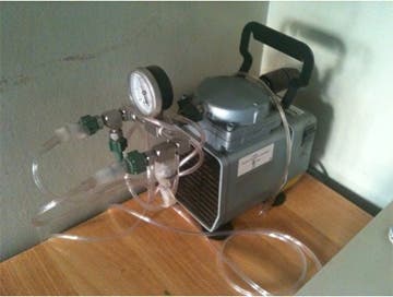
- Jet nebulizer (Air compressor as seen in Nicaragua and most commonly used worldwide)
- Most commonly used here is the Pariproneb with 50 psi pressure (much higher than Nicaraguan which was around 15 to 20 psi)
- Vibrating Mesh
- New technology as of a couple of years age
- Aeroneb Solo System (Not widely used)
- Very cool!
- Disposable piece that would cost $40
- Would break up into adequate particles sizes of 3-5 microns
- Piece connected to a controller with batteries and frequency generator (set)
- Can be placed into series with other machines such as ventilators
- Medicine is gravity fed through a vibrating mesh that breaks up the particles- mesh is a one-way valve
- Solves dosage problem: device is breath-actuated so whatever medicine is used is ensured to be in the patient.
- Problem is that reservoir gets clogged if the medicine isn’t breathed in fast enough Brainstorming ways to stop vibrating mesh if too clogged; can possibly be detected through shining an LED through it. Or if controller can only trigger for next breath?
- Currently used with corrugated tubing can replace with see-through to look at dosage that is in it.
- Need sealed area
- Ideas to prolong life of disposable piece is to create a one-way valve mask that can be attached
- Ultrasonic
- Widely used before but it would steam copiously and would also “rip” particles rather than just breaking them up into too small particles
- Stopped being used in the ’80s and ’90s; no considerable efforts have been put into improving technology so still room for improvement and play.
- Idea: common reservoir with multiple outlets for multiple patient use??
- Nurse described E-flow compressor
- Only used for astroneum medicine
- Works similarly to vibrating mesh
- Patients having trouble with cleaning it
- Fun Fact: Teenage patient used it to inhale marijuana!! (what is the world coming to.. :) )
More details coming soon!
by Caroline Hane-Weijman
Broken nebulizer
by Caroline Hane-Weijman
Some useful sites that were recommended to us by Jose to explore:
- www.instructables.com
- www.asknature.org
- www.hackaday.com
- www.thingiverse.com
- Respiratory Drug Delivery Conference
- Supersoakers
- Car wash accessories
Another device Jose helped us come across which almost basically solves our issue… Aeroeclipse!
- Diaphragm idea that incorporates a breath actuated valve that will direct air from air compressor through medicine when breathing in, and will redirect away while not breathing so only air, no medicine is wasted and therefore dosage delivery can be controlled.
Background Discussion on the Capnography Technology
by Shan Tie
The use of capnography was first considered as a way to monitor dosage. Caroline had initially discovered this technology in the context of its usage for anesthesia and intensive care. The capnogram directly measures the inhaled and exhaled concentration or partial pressure of CO2 produced by the patient. Furthermore, the device can indirectly measure the amount of arterial CO2.
There are five major physical methods for detecting CO2; however, the least expensive and most popular method for CO2 detection involves using IR technology.
The actual device interface includes a mask that contains an IR light source, some filters and focusing lenses, and an IR detector. The IR source shines IR light through the cloud of CO2 particles produced by the patient. CO2 selectively absorbs 4.3 micron IR light. The absorption amount is directly correlated to the CO2 concentration and thus the amount detected can be compared to a known standard of CO2.
The information that the capnography provides includes CO2 production, pulmonary perfusion, alveolar ventilation, respiratory patterns, and CO2 elimination. These data is presented as the inspired and/or expired CO2 plotted over time (Kodali, capnography.com).
This technology initially appealed to us because it was a technology that had concepts based very much like the pulse oximeter, is already interfaced with a mask, and is used to measure gas production. Our belief was that if we could place the sensor close between the drug outlet of the mask and the nose of the patient, the patient’s breathing can be monitored by his CO2 production and we can assume due to proximity of the drug outlet to the patient’s nose, that he would be effectively breathing the medicine. We can then use this to track the breathing of the patient over time and count up the amount of time that his CO2 production was above a minimal threshold (to account for adequate breathing) until it totally 10 minutes.
After speaking with Brian Walsh, a respiratory specialist at the Children’s Hospital Boston, we discovered some limitations in using capnography. We intended on using this technology for patients under 5 years of age. Currently, the capnograhy either directly measure the CO2 in the mask or takes measurements from side stream line that pulls out samples from the mask. Unfortunately, the amount of CO2 production by these young patients will be too low for any capnography device made cheaply to detect. Furthermore, the capnography device requires a near perfect seal between the patient and the mask. However, the current masks contain vents to allow the release of the CO2 and a perfect seal for infants is nearly impossible. Given these limitations, we decided we needed a more feasible and reliable method for monitoring dosage.
Background on Vibrating Mesh Technology
by Shan Tie
During our visit to speak with Brian Walsh, he introduced a new nebulizer that is based on vibrating mesh instead of the standard air jet from the compressor pump.
The new aerosolizing technology was implemented in a nebulizer made by a company called Aerogen. The structure of the device is a thin mesh material with ~1000 holes. The device is battery powered to cause the mesh to vibrate at 100,000 times a second. This vibrating motion is a sieve-like motion that draws the albuterol liquid sitting above the mesh through the holes like a pump and effectively aersolizing the liquid droplets into consistently sized, aerosolized particles (Aerogen.com). The aersolized drug will then fall down due to gravity and will collect in the chamber of the nebulizer until the patient actively inhales the drug.
This technology seemed promising because it addressed two major pitfalls in the current nebulizer design. One, it created uniform aersolized particles such that it is of a breathable size that will allow for effective delivery of the medicine to the appropriate areas of the patient lung. Second, the breathe-actuated feature of the device allows for more accurate monitoring of dosage because no medicine is actively pushed out of the chamber without the patient breathing it in- thus leading to a lower medicine loss and allows for more accurate measure of how much drug is breathed in.
Ultrasound Nebulizer Background
When we visited Brian Walsh and Chris Hug, they also mentioned a type of nebulizer that operated by sending ultrasonic waves through the drug. These were developed around 30 years ago, and consist of a piezoelectric plate which transmits high-frequency vibrations through a liquid. These devices output a far higher volume of nebulized material than traditional jet nebulizers, and since the frequency can be very easily controlled do not have the problem of varying particle size encountered by jet nebulizer. At first we had the idea to utilize the high-volume output by collecting it in a reservoir from which multiple patients could be nebulized. However, we were told that though the particle size was uniform, it could often be too small - meaning that either that the particles would only be effective on deep-lung conditions or that they would not settle in the lungs at all but be immediately exhaled. In some cases, the ultrasonic nebulizers actually ripped up the molecular structure of the drug, rendering it useless.
We decided that considering the far higher cost of ultrasonic nebulizers they may not have much advantage over the jet method - especially since clinics in Nicaragua already have air compressors and compressed air outlets.
Design Update: Playing with Nebulizer Reservoir
- Drilling holes in Tupperware reservoir
Caroline bought some Tupperware that we could use for vapor reservoirs. Today in D-Lab, we drilled a hole in the bottom to serve as a connection to the medicine chamber. Grace is also going in later today to drill holes in the side of the Tupperware® to place a laser and photo detector.
- Condensation in the reservoir
Playing around with the nebulized vapors in the Tupperware®, we noticed a few things. There was condensation buildup on the side, and we wondered if a non-static coating would ameliorate the problem. Also, pressure could build up in the reservoir if closed, so we need to think about whether multiple users would prevent this pressure build up or whether there needs to be some release valve.
- Learning about how to measure vapor size
There seems to be multiple ways to measure vapor size. Paul H. talk to us about the one way he does so for the Aerovax project. A laser sits on a stand and shoots a beam of light towards a photosensor. If particles are in the way, then they will diffuse the light and less light will reach the sensor. The larger the particles–> more light scattered–>less light detected by the photosensor–>lower resistance in the detector–> higher voltage outputted and recorded. Paul built and wired this system that we will use.
We want to measure relative vapor size of particles coming out from the nebulizer directly compared to particles that have been sitting in the reservoir to see whether time in a reservoir causes clumping of particles. This is important because Dr. Brian Walsh of the Children’s Hospital mentioned that particle size will dictate efficient delivery of the medicine in to the lungs. So we want to ensure that our reservoir is not changing the particle size.
Today, we were orientated to the setup and we plan on doing some tests during the week.
Background on Anti-Static Coating for the Reservoir Surface to Minimize Aerosol Particle Coagulation
by Shan Tie
Anti-Static Methods
Chemical solutions to static electricity: http://www.explainthatstuff.com/howantistaticcoatingswork.html
Glass pipes with a protective antistatic coating: (PDF)
The optimal composition of the applied film is found to be: 50% SnCI~.5H20 with a concentration of 1% SbCI3.
Anti-static coating and its method of preparation:
This patent talks about composition of anti-static material composed of a synthetic resin base without any metallic particles. However, it is in the context of using this coating for the fuselage of airplanes; therefore it might be a bit more than what we need for coating our nebulizers.
%%%
Found various anti-static sprays:
-
Aeros anti static spray (END096000) Category: Surface Cleaners
Found various anti-static tape:
-
Dadas Tapes 1662-05 - Anti-Static Transparent Tape, 3" Core, 1/2" …
-
Botron B1651 (1/2"x36yd Clear ESD Tape) - 1/2"x36yd Clear ESD Tape
Pictures of our Reservoir Prototyping Round 1
by Caroline Hane-Weijman
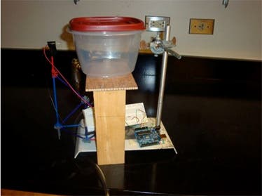
Vapor laser sensor connected to the Arduino can measure particle size and concentration
We need to explore a valve system so that the pressure does not get too high inside the reservoir.
Next step: Build the patient tube with a one-way valve and another vapor sensor!
Experimental setup with patient tube, one-way valve, and second vapor sensor


