
One-Way Valves
by Mary Jue Xu
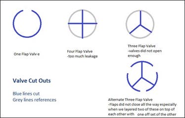
Designs for valve cut-outs
Part of our design is to have a breath-actuated one way valve. In other words, a valve that will open only when the patient breaths and only opens one way.
At first, our group was looking online to try and find one way valves to buy. The majority of them that we saw were used for CPR, so we were concerned that those valves required more pressure than a baby’s breath could open.
Then in class Jose introduced us to a way of simply making one way valves cheaply. The D-Lab health team from last year also worked on this as well, so I talked to one of their members, Luvena. Their team used a thin plastic bag for the valve and cardboard cut-out rings adapted to whatever tubing being used. A problem the group ran into was that the flap did not close completely.
Shan and I tried some one way valves. For holders, Caroline had the idea of using the bottleneck part of water bottles and the O-rings on the top as holders. Also, Caroline and Grace found mesh to put behind the flap so that it would allow air flow one way but prevent the flap from opening both directions. They chose white mesh because they thought it would look cleaner to patients.
In class, Shan and I found that one large flap was better cutting the circle into four flaps. The four-flap system had a lot more leakage if everything did not align during assembly. Also, three-way flaps were held too tightly on the rings.
As Grace will explain in her post, Ryan, an instructor from D-Lab was kind enough to lend us some pressure valves that open upon reaching a certain pressure. We have decided to hold off on the manually made one way valves for now. Since our design is unique in that it is all pressure modulated, we are first focusing on proof of principle before we think about decreasing costs and local manufacturing.
Preliminary Vapor Quantity Testing
by Shan Tie
One of the things we mentioned as an important feature for our new nebulizer design was to incorporate a better method for measuring dosage. Our design will attempt to address that by adding a breath-actuating feature (medicine only flows out when a patient inhales) in conjunction with a vapor sensor near the mouthpiece to sum up the times when vapor is passed through from the reservoir to the patient.
Today, Mary and I worked on creating the physical breadboard and the Arduino code for our sensor. The sensor itself consists of a LED light, a light sensor, the Arduino, and the breadboard. The set-up of our system works off of the current system created by Paul and his team. Our physical construction will be described in more detail by Mary. A modification we included in our design was to replace the laser light source with a LED light. The original design needed a LED light because the sensor was placed at a much farther distance away from the light source and the detection threshold of the sensor depended on a minimum level. However, after speaking with Paul, we realized that the distance we will be working with (the diameter of a tube, ~2 cm) is small enough to allow us to use a LED light. We modified the Arduino code from Paul’s original detector and added code that specified turning on the LED.
Arduino code:
int redPin = 7; // sets the output serial port for the LED light
int sensorPin = 0; // sets the input serial pin
int sensorValue = 0; // sets the initial input value at the pin as 0
void setup() { // how to start the set-up code
pinMode(redPin, OUTPUT); // defines the output variable name as “redPin”
pinMode(sensorPin, INPUT); // defines the input variable name as “sensorPin”
Serial.begin(9600); // defines the “baud” rate (transfer of data rate)
}
void loop() { // how to start the operating code
digitalWrite(redPin, HIGH); // defines the digital output from the arduino board to the LED
sensorValue = analogRead(sensorPin); // defines analog output from the sensor as “sensorValue”
Serial.println(sensorValue); // displays the sensorValue in a running stream of numbers
}
We created a special testing tube for our sensor and LED (Mary will describe). We tested the sensitivity of our sensor by flowing nebulized water into our test tube and observing the output measures from our sensor. Our system is very stable without any aerosolized particles flowing–in our test run, the output signal was 437. When we ran nebulized water, the level rose to 452. When we stopped flowing air into it, the levels never returned to the initial baseline value (443)– this is due to a degree of condensation that remains both on the walls of the tube and on the sensor and LED light. When we resumed flowing nebulized water, the signal output rose to 455. However, the changes between when the nebulizer is on and off were 15 and 12, respectively. This seems to show that there is consistency in our devices in our preliminary tests.
Next steps:
It will be interesting to carry out the previous experiments further and see if the change remains consistent once the walls becomes saturated.
We will need a way to sum up the amount of particle that flows through over time.
We need to create a standard for the amount of particles flowing through based on the output.
Vapor Sensor: Physical Setup
by Mary Jue Xu
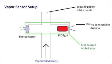
Vapor sensor setup
Today we made an tested our first prototype of a vapor sensor. It was really excited to get the Arduino code, wiring, and initial test set up. The idea behind the vapor sensor is to measure dosing. By measuring interference of a light to a photodetector, we can tell how much time and possibly volume of vapor the patient has breathed in from the breath-actuated nozzle.
We initially sought help from Paul H, who works for IIH on the Aerovax vaccine. I remember seeing him testing vapor size earlier this semester.
Today to build the initial vapor pressure prototype, we connected 4 tube ends with black electrical tape. Then we placed the photodetector and the LED light in tubes facing each other. We covered those two tubes with black tape in order to block out ambient light. This way, the photodetector could pick up the LED light more accurately. So vapors flow through one direction and the sensor picks up data in the perpendicular direction.
Photos of Testing
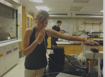
Testing the nebulizer
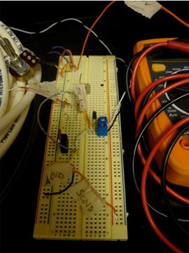
Breadboard circuit
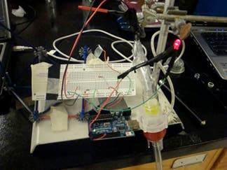
Complete setup
Prototyping and Testing
by Caroline Hane-Weijman
We spent the day in D-Lab playing with all the wonderful toys Rob provided us to create the different modules of our designing and testing them. The main three components we worked on today were:
Vapor Sensor- This is to measure dosage received by the patient after the breath-actuated one-way valve
Solenoid Valve- This valve is placed before the nebulizer cup as a way to divert the compressed air flow from going through the medicine when the pressure inside the reservoir gets too high.
System Pressure monitoring of the System- This looked at the interplay between the air compressor, pressure of the reservoir, and the activation/“cracking” of the one-way valves.
We got a lot of testing done and have these components at least working separately. Next step–> Put it together!
I looked specifically at the System Pressure monitoring of the System. We drove the air compressor by a voltage source, connected it to the nebulizer cup (using any type of connectors we could make work), placed a Vernier Gas Pressure sensor inside the reservoir that communicated with a LoggerPro and the accompanying software, and connected the reservoir to a tube with a one-way valve placed at the end. We were exploring 0.07 psi and 1.5 psi valves. The following labeled photograph shows the experimental setup!
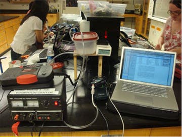
Experimental setup
Observations
- Reservoir Lid pops when the reservoir is at approximately 104.4 kPa
- Found that around 102. kPa the 0.07 psi valves opened. i.e. would open very easily and before medicine was able to get through the tubing
- Used a 1.5 psi valve, which before could not be breath actuated, but after pumping pressure through it and kept the pressure in the range of 102 kPa and 103 kPa, was able to be breath actuated- want to go with this valve for now.
- Coagulation is a problem- by the time it reaches the outlet tub it condenses again.
- The system kept leaking which is why the pressure was constant while flowing air through the system without opening the valve, however when we made attempts to seal these leaks, the pressure would quickly increase and pop the lid of the container.
- While sealing leaks, pressure was able to be maintained relatively constant when we activated the valves (breathed in) which is positive. The highlighted portion of the graph below shows consistency due to breathing in (while the others are due to leakage). Peaks occur when the lid pops off the container.
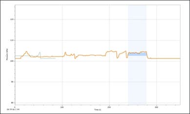
Pressure-vs.-time data
General Project Overview & Ryan Assistance
Recently we refined our final design idea to the point where we know exactly what we need to build and what tests we need to run - as shown in the wonderful blog posts below. Much of this was due to the help of Ryan, who lent us pressure control equipment and gave us some great ideas for our setup and experimentation.
The general ethos behind our final product is that we’re proving the concept of our design with high-quality equipment that can be scaled down in cost and complexity if the concept proves to work. Our overall goal is to create a nebulizer that:
-
Can be used on multiple patients
-
Is very efficient in its use of medicine
-
Allows some level of dosage monitoring
The way we decided to do this was to create a nebulizer with a central reservoir from which multiple patients’ tubes could feed off. It also aims to be breath-actuated by the patient, i.e. medicine only comes out if the patient breathes in. To do this, we want to use one-way valves on the end of each patient’s tube and control the pressure in the reservoir such that it is just under the cracking point of the one-way-valves. This way, the patient only needs to apply a little pressure by breathing in for the valve to open and them to receive the medicine.
The way the pressure can be kept at this rate is through a control system run through the Arduino. The Arduino takes input from a pressure sensor in the reservoir and based on that decides whether to open or close a valve between the air compressor and the nebulizer cup. If the pressure is too great, the valve opens and directs the compressed air away from the nebulizer. As pressure starts to go down, the valve closes, letting more air through the nebulizer cup. With an effective control system the pressure in the reservoir could be kept reasonably constant.
Fancy equipment that Ryan has given us:
- Several different one way valves, with different cracking pressures (0.07psi, which is adult breathing pressure, 1.5 psi, and I think a 10 psi. Note: all of these can be breath actuated, the pressure on the other side just has to be a little bit lower than the cracking pressure. One of our experiments will be to determine whether a high or low pressure reservoir works better). The one current problem with these one way valves is way they fit in line with the pipes - we don’t really have good couplings for them. Some investigation and hardware store shopping is needed.
- A fancy 3-way solenoid valve. Basically what this does is it receives an input from the Arduino, (on or off) and depending on what that input is switches the flow of air from one outlet to another. This goes behind the nebulizer - the input is the compressor air, one output is the nebulizer, and one is left to the open air. So when we need to decrease pressure, the Arduino will tell the valve to switch to the open air output.
This does require wiring up some circuitry - the solenoid valve cannot run on the low (5 V) Arduino voltage, it needs at least 12 V. Though this is now made a lot easier by the fact that Ryan has given us all the necessary parts and a picture of a working breadboard in his lab that uses the same circuit.
Ryan advised us that when testing the solenoid valve, instead of hooking it up directly to receive input to the pressure sensor, we should use a ‘fake’ pressure sensor input into the Arduino (e.g. a pot) that we can directly control to check the code works instead of relying on the pressure sensor straight away.
D-Lab Showcase!
by Caroline Hane-Weijman
Yesterday, D-Lab had its end of the year showcase at the MIT Museum, featuring all the D-Lab class projects. D-Lab Health gave the other classes a run for their money :) The neb team managed to get all the individual components working, including the solenoid valve, the pressure sensor, and the vapor sensor (all with code), before the showcase, although it was a rush to the finish! Shan did a great job representing our team in the one-minute pitches, and people seemed to like the idea.
We still need to work on the interplay between the components but we were having issues with leakage in the system and therefore the pressure in the system was relatively constant when we tried to seal the end of the tube. We also have to retrofit the tiny valve to the large tube for the mask- but for demonstration purposes on Wednesday we are considering showing it as two different components as we do not have the opportunity to get the right diameter valve in time. We will continue working until Wednesday— come see us present in class in detail!!
Vapor Quantity Testing Part 2
Vapor sensor also includes the ability to turn on a “dosage LED”- in other words, this light turns on when the total amount of time the patient is inhaling medicine satisfies a requisite number. Currently, the code takes in a given threshold value that determines when the patient is inhaling medicine and also a set dosage time of 10 seconds. In reality, the threshold number will need to be calibrated closer to the levels that is seen from a person’s inhalations and to take into account noise from humidity in the air and inaccuracies in the measurements. Furthermore, the dosage time will be actually ~10 minutes to correspond with current standard dosage times (it’s shorter here for proof-of-concept needs).
Arduino code:
int redPin = 7; // sets the output serial port for the sensor Red LED light
int dosePin = 4; // sets the output serial port for the dosage dose LED light
int sensorPin = 0; // sets the input serial pin
int sensorValue = 0; // sets the initial input value at the pin as 0
int lastsensorValue=0; // defines the variable to store the last sensorValue
int threshold = 300; // set by user as the baseline value needed to reach for nebulized medicine
long startTime; // defines the start time
long elapsedTime; // defines the elapsed time
int total=0; // defines the variable the sums up the time for when the sensorValue is above threshold value
int fulldosage = 10000; // defines the dosage time (in milliseconds) for a complete dosage
void setup() { // how to start the set-up code
pinMode(redPin, OUTPUT); // defines the output variable name as “redPin”
pinMode(dosePin, OUTPUT); // defines the output variable name as “dosePin”
pinMode(sensorPin, INPUT); // defines the input variable name as “sensorPin”
Serial.begin(9600); // defines the “baud” rate (transfer of data rate)
}
void loop() { // how to start the operating code
digitalWrite(redPin, HIGH); // defines the digital output from the arduino board to the LED
digitalWrite(dosePin, HIGH);
sensorValue = analogRead(sensorPin); // defines analog output from the sensor as “sensorValue”
if (sensorValue >= threshold && lastsensorValue <= threshold){
startTime = millis();
}
if (sensorValue <= threshold && lastsensorValue >= threshold){
elapsedTime = millis() - startTime;
//Serial.print( (int) (elapsedTime / 1000L));
}
lastsensorValue = sensorValue;
total = total + elapsedTime;
elapsedTime = 0;
if (total >= fulldosage) {
digitalWrite(dosePin, HIGH); // turns on dosage dose LED only when the desired time is fulfilled
}
else{
digitalWrite(dosePin, LOW); // ensure that dosage dose LED is OFF when the desired time is NOT fulfilled
}
Serial.println(sensorValue);
}
Mini Update
As few days ago, we presented our design in class. It was a lot of fun showing our design and seeing other groups’ work.
This summer, we will be in China, New York, and Boston, so maybe some of us can continue building and testing over the summer!


