
Chad Keever, Projectile Launcher
Kendall McConnel, Control of a Plotter
Jonah Elgart, Guidance by IR Beacon
Miki Havlickova, IR Remote Control
Jessica Bowles-Martinez, Guidance by Light
Matt Seegmiller, Master/Slave IR Control
Jitin Asnaani, Invertible Robot
Jitin’s Robotics Web Page!!!
Background
Hi! My name is Jitin Asnaani. I’m a Roboticist wanna-be, and as such I decided this term to take this cool class called the ESG Robotics and Mechatronics Seminar. This Web page is dedicated to the story of the first robot I made by myself (well, mostly by myself). I made this robot to satisfy the last required project of the class, which was “to design and construct a working device with at least vaguely-interesting capabilities” and then, to build a Web page to show it off. All the specifics, including the type of project we wanted to work on, was left entirely up to our imagination.
So What Was My Bright Idea?
Being a person of little experience with Lego and electronics, I decided to work on a modest project which would be both interesting as well as instructive. Thus came about the idea of an invertible robot: Invertibot. Essentially, the plan was to design and program Invertibot so that it could demonstrate its ability to perform a series of specific movements, performing the same movements whether placed rightside-up or upside-down.
Getting Around
The first decision I made as to the structure of the robot was to use wheels as the method of locomotion. On the front of the robot I put two large wheels, one on the left and one on the right, driven by individual motors. Due to the constraint that I did not want to use an excessive number of Legos, I made the width of my robot fairly small. This, however, caused two potential problems: firstly, the motors for the wheels could not be placed adjacent to each other since they were relatively large; and secondly, the gear train had to be sufficiently powerful yet fairly compact, so as to fit in to the limited space. To accomplish the problem with the motors, I simply placed one motor on the top of the robot, and the other on the bottom. Each one, as I said, operated on a different gear-train. As for the gear-train itself, making it compact created problems related directly with the limitations of Lego, in terms of the limited options for putting Lego pieces together so that they mesh perfectly with each other and with the technical parts (gears, shafts, etc.) required to create motion. As for the back of the robot, there I installed two (much smaller) caster wheels, one on the topside of the robot and the other on the bottom. The result was that whether or not the robot was inverted, locomotion is always provided by two driving wheels at the front of the robot and one caster wheel trailing at the back.
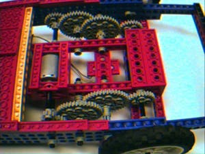

The gear train (left); a caster wheel (right).
What’s Up?
With the locomotive components of the robot constructed, the obvious question that to ask was this: “how will the robot differentiate between being rightway-up and upside-down?”. To accomplish this “detection of vertical orientation”, as I like to call it, I installed a very interesting type of sensor on the robot. Basically, this sensor consists of four pieces of wire, horizontally aligned above each other, running from outside the plastic sensor case and ending in the interior of the sensor case. Within the sensor case is a metallic ball, whose diameter is large enough to touch any two adjacent wires, but no others. The movement of the ball is basically restricted to vertical movement only due to the constrained width of the sensor. The result is that if the sensor is rightside-up, current could only flow through the circuit consisting of the bottom-most wire, the ball, and the second-bottom-most wire, while if it was upside-down, current could only flow through the topmost-wire, the ball, and the second-top-most wire. With this in mind, a pair of connection wires was attached to the two lower wires, and detection of the flow of electricity through this wire was used in the program (outlined below) that controlled the robot.
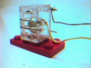
The “metallic ball” sensor.
Controlling Invertibot
Though ideally I would have liked to place touch sensors on the periphery of the robot’s frame so that it could tell when it had run into walls and other external objects, time restrictions dictated otherwise. Thus the program (C) I wrote to control the robot was simple, and designed to do two things: firstly, to use the sensor readings to tell what orientation (rightway-up or upside-down) the robot was in; and secondly, to command the robot to perform a small series of movements which would not occupy too much straight but would demonstrate the robots ability to move in a specific series of movements no matter what the orientation. The program was downloaded from a network computer to the robot’s handiboard, which is really a small motherboard. The handiboard controls all the attached electronic components on the robot, allowing a user to logically control his robot with the specific programs he writes to manage the sensors and motors.
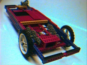
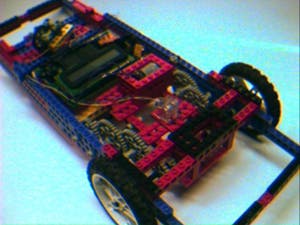
Rightside-up and upside-down views of invertibot.
Future Robots?
And that’s the story of Invertibot: controlled by a handiboard and equipped with an orientation sensor and two motors on the front, the Invertibot is the product of three weeks of trial-and-error, not to mention some ingenuity and a bit of laboratory tom-foolery. I guess that’s it: Invertibot is the first breakthrough in robotics and AI for me, being the first robot I ever built and programmed myself. I hope to work on more robots in the near future, and on that account, I’ll hopefully need to update this page soon. Till then, thanks for dropping by. I hoped you liked the story of the Invertibot. Bye!


