Main | Hardware | System Model | Linearized Control | Nonlinear Control | Movies | Technical Details | Credits
The two major sections of the Levitator are the plant/sensor structure and the electronics and computer which control the structure.
Plant
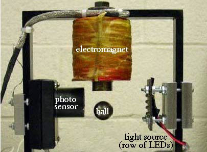
Levitator in action (above) and its schematic representation (below).
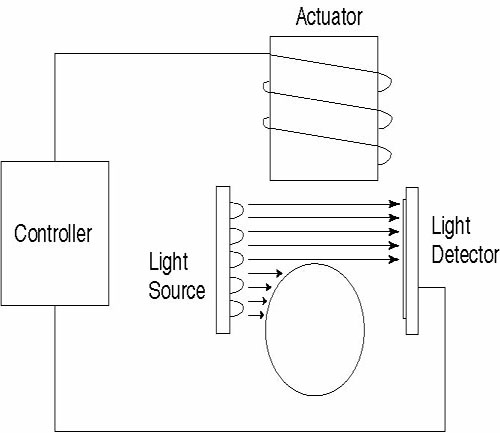
The plant consists of the actuator, an iron-core electromagnet and the steel ball bearing levitated by the electromagnet, along with the sensor that sends position to the control circuitry.
Current through the coils of the electromagnet induces a magnetic field in the iron core. In conjunction with the sensor and control electronics, the electromagnet exerts a force on the steel ball so as to keep it floating at a given height.
To control the position of the ball, the control electronics need to know the actual position of the ball at any given time. In this device, position is sensed by a light source and detector acting in combination. Light from the source striking the detector creates a current which is transduced into a voltage. The higher the ball is, the less light passes above the ball to the detector, translating to correspondlingly less voltage. In the control electronics, this voltage is translated into a position reading.
Control Electronics
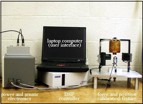
Control circuitry, with the plant structure.
The control circuitry consists of a set of power supplies and amplifiers connected to a control computer. The control computer is a dedicated digital signal processor (DSP), programmed through the laptop. The power supplies and amplifiers receive the signal from the position sensor and send power to the actuator. An input/output box wired to the analog to digital and digital to analog converters on the computer allows the power electronics and the computer to talk to one another. In the photograph above, the ball rests on a micrometer/force measurement apparatus used in calibrating the system.
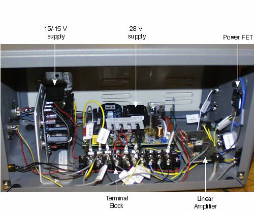
The power electronics box.
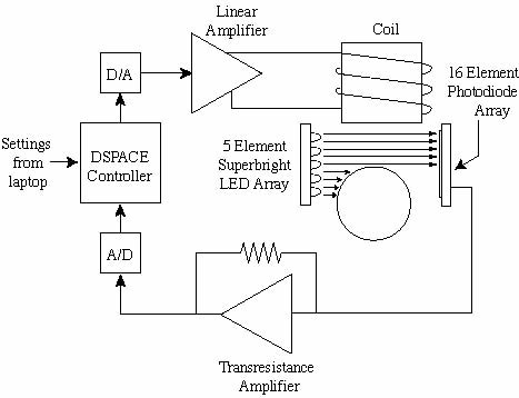
Combining the plant and control electronics, the schematic for the whole system is: