
| « Previous: Return to Assignment 3 description | Next: student work sample » |
By Elena Jessop, Dawn Wendell and two anonymous MIT students

The Fractal Tree Bag
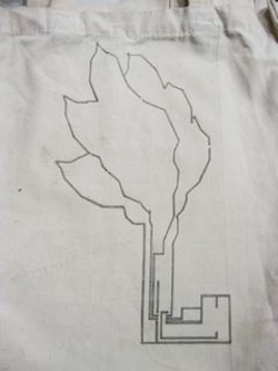
Our concept was to make a canvas bag with a fractal tree design that integrates sensor inputs and LED outputs. The two sensors are (1) a pressure sensor at the bottom of the bag and (2) a touch sensor integrated into the “grass” at the bottom of the tree motif. The outputs are three LEDs.
Video of the Fractal Tree Bag in action: dawnw2000. “Fabric PCB Bag.” YouTube. March 3, 2010. Accessed December 2, 2010.
Circuit Design

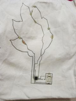
An initial circuit sketch (left) and circuit diagram (right).
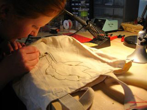
This design was translated into Illustrator and combined with the Tree Motif. The components were then soldered on and encased in epoxy. The soldering was challenging because the conductive fabric would melt if it got too hot. Therefore, some gaps had to be closed with additional wires.
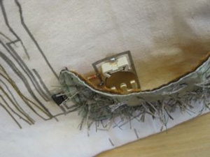
The finished lasercut pieces before soldering (left), and after soldering and epoxy (right).
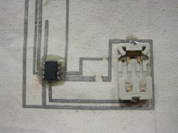
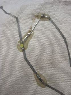
Details of soldered and epoxied components.
Tree Motif Design
The tree motif was chosen because we wanted to integrate fractal patterns into the design. The fractal idea came from this website which talks about polygon fractals.
- McManus, Jerry. “Polygon Gardens.” Director Online.
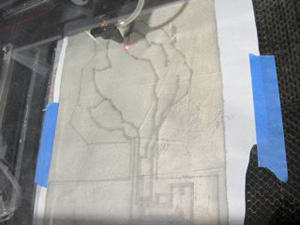
The fractal tree was coded in Rhinoscript. The tree was laser cut from 3 separate iron on fabric layers. The first was the conductive fabric, the remaining two were satins.
Tree Motif file, with conductive fabric circuit in blue, and the fractal tree in red.
Large (850x1074) image of the Tree Motif image
We used a tiny iron to attach the two fabric layers over the conductive layer to avoid melting the epoxy covered surface mounted leds and resistors.
The Sensors
There are two sensors on the Fractal Tree Bag, the pressure sensor and the touch sensor.
Pressure Sensor
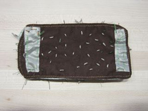
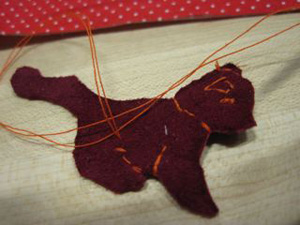
The pressure sensor is a sandwich of conductive fabrics separated by foam and surrounded by felt. This sensor was placed at the bottom of the bag so that it would respond to anything placed in the bag.
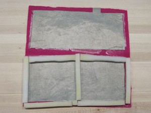
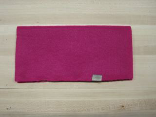
The pressure sensor: construction (left) and finished (right).
However, when the pressure sensor was installed in the bottom of the bag, testing showed that the pressure sensor was too sensitive. A layer of neoprene was added with holes cut in it to decrease the sensitivity.
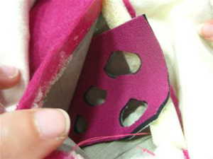
A neoprene layer was added to the pressure sensor to decrease its sensitivity.
Touch Sensor
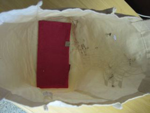
The touch sensor is created by sewing conductive and non-conductive threads onto a fabric background. When the sensor is touched, the threads flatten out and make contact, decreasing the resistance across the sensor. The touch sensor was sewn onto the bag to cover the battery holder but the top edge wasn’t attached so that the battery can be accessed.
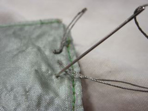
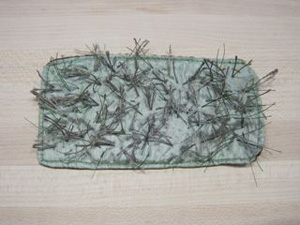
Photos of the Touch Sensor
The AVR Programming
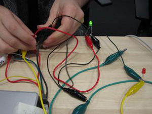
The code was designed to flash between all the outputs when there were no inputs, and if an input was detected, then only one LED would light up. The code was first tested on one of the pre-made circuits from the in-class demo before being loaded onto the ATtiny13 microcontroller installed on our bag circuit.
Our code (TXT)
Lessons Learned
- We cut the circuit onto the wrong side of the conductive fabric so the circuit was cut but the paper was not. This was a problem when trying to peel off the paper only in select locations so it could be ironed onto the bag. We solved this problem by taping over the other side of the circuit, peeling off the parts that we didn’t want to be ironed, and then ironing over the tape. It worked, but definitely wasn’t the ideal case.
- Soldering surface-mount components onto conductive fabric is hard because if the fabric overheats, it burns away. The best technique that we found was to tin the pieces heavily, use lots of flux, and be quick and careful with the soldering iron.
- In attaching our two switch sensors, we originally intended for the switch to close a circuit to ground, and pull the microcontroller pin low. However, we discovered that the open circuit was also read as “low”…most of the time. The floating end of an open circuit was variable, generally reading low but occasionally collecting a voltage value high enough for the microcontroller to read as “high,” despite the pin not being pulled to power. We solved this problem by connecting a 10K resistor between the input pin and ground, then attaching one side of the sensor to an input and one side to power. With this arrangement, the pin is pulled to ground when the switch is open. When the switch is closed, the direct connection to power has less resistance than the connection to ground, and so the pin is pulled high.
- Originally we wanted to do the fractal tree (red layer) in leather, we test cut a perfect square of leather at 100power/15speed in the lasercutter. However, our pattern was so delicate that the pieces either burned or did not cut. I think with more time we would find the correct setting to cut these lacy leather kinds of pieces in the lasercutter. Instead we used two silky fabrics to make overlapping layers for the trees these were cut at 50power/50speed
Scenes from the project.
Contributions
- Elena: AVR Programming, lasercutting
- Anonymous student: design of the conductive paths, design of the tree, lasercutting
- Dawn: initial circuit design, pressure sensor, documentation
- Anonymous student: stroke sensor, artistic elements
| « Previous: Return to Assignment 3 description | Next: student work sample » |


