MAS.962 | Spring 2010 | Graduate

Special Topics: New Textiles

Assignments and Final Project

Assignment 3: "Hello World" Fabric PCBs, Part 2

« Previous: Assignment 2: “Hello World” Fabric PCBs, Part 1 Next: Assignment 4: Yarn »

For this assignment you will work in teams to create an artifact that includes a fabric PCB. The artifact should include an ATtiny13 microcontroller, at least two outputs and at least one digital (switch) input. A picture of the circuit that I made is below. You can use this circuit as a starting point, but you should not just turn in an identical copy. You should modify my circuit in some way and/or incorporate it into a larger project by, for example, sewing it into a garment.

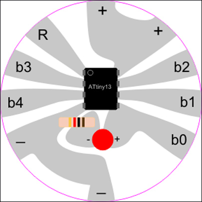
An example fabric PCB circuit.

With your team you should create a webpage that documents your project. Your page should include pictures, including at least one close up of your PCB and one image that shows the entire project, and a paragraph about your experience. Also create a short video of your project in action; post the video online (Vimeo, YouTube, or your own site) and include a link to your video in your documentation page.

Sample Student Work

These samples are presented courtesy of the students and used with permission.

Fractal Tree Bag

PCButterfly

« Previous: Return to Assignment 3 description Next: student work sample »

By Elena Jessop, Dawn Wendell and two anonymous MIT students

The Fractal Tree Bag

Our concept was to make a canvas bag with a fractal tree design that integrates sensor inputs and LED outputs. The two sensors are (1) a pressure sensor at the bottom of the bag and (2) a touch sensor integrated into the “grass” at the bottom of the tree motif. The outputs are three LEDs.

Video of the Fractal Tree Bag in action: dawnw2000. “Fabric PCB Bag.” YouTube. March 3, 2010. Accessed December 2, 2010.

Circuit Design

Circuit design drawings, by hand and then done with a computer.

An initial circuit sketch (left) and circuit diagram (right).

This design was translated into Illustrator and combined with the Tree Motif. The components were then soldered on and encased in epoxy. The soldering was challenging because the conductive fabric would melt if it got too hot. Therefore, some gaps had to be closed with additional wires.

The finished lasercut pieces before soldering (left), and after soldering and epoxy (right).

Details of soldered and epoxied components.

Tree Motif Design

The tree motif was chosen because we wanted to integrate fractal patterns into the design. The fractal idea came from this website which talks about polygon fractals.

The fractal tree was coded in Rhinoscript. The tree was laser cut from 3 separate iron on fabric layers. The first was the conductive fabric, the remaining two were satins.

Line drawing of the tree design with overlaid conductive fabric circuit.

Tree Motif file, with conductive fabric circuit in blue, and the fractal tree in red.

Large (850x1074) image of the Tree Motif image

We used a tiny iron to attach the two fabric layers over the conductive layer to avoid melting the epoxy covered surface mounted leds and resistors.

The Sensors

There are two sensors on the Fractal Tree Bag, the pressure sensor and the touch sensor.

Pressure Sensor

The pressure sensor is a sandwich of conductive fabrics separated by foam and surrounded by felt. This sensor was placed at the bottom of the bag so that it would respond to anything placed in the bag.

The pressure sensor: construction (left) and finished (right).

However, when the pressure sensor was installed in the bottom of the bag, testing showed that the pressure sensor was too sensitive. A layer of neoprene was added with holes cut in it to decrease the sensitivity.

A neoprene layer was added to the pressure sensor to decrease its sensitivity.

Touch Sensor

The touch sensor is created by sewing conductive and non-conductive threads onto a fabric background. When the sensor is touched, the threads flatten out and make contact, decreasing the resistance across the sensor. The touch sensor was sewn onto the bag to cover the battery holder but the top edge wasn’t attached so that the battery can be accessed.

Photos of the Touch Sensor

The AVR Programming

The code was designed to flash between all the outputs when there were no inputs, and if an input was detected, then only one LED would light up. The code was first tested on one of the pre-made circuits from the in-class demo before being loaded onto the ATtiny13 microcontroller installed on our bag circuit.

Our code (TXT)

Lessons Learned

  • We cut the circuit onto the wrong side of the conductive fabric so the circuit was cut but the paper was not. This was a problem when trying to peel off the paper only in select locations so it could be ironed onto the bag. We solved this problem by taping over the other side of the circuit, peeling off the parts that we didn’t want to be ironed, and then ironing over the tape. It worked, but definitely wasn’t the ideal case.
  • Soldering surface-mount components onto conductive fabric is hard because if the fabric overheats, it burns away. The best technique that we found was to tin the pieces heavily, use lots of flux, and be quick and careful with the soldering iron.
  • In attaching our two switch sensors, we originally intended for the switch to close a circuit to ground, and pull the microcontroller pin low. However, we discovered that the open circuit was also read as “low”…most of the time. The floating end of an open circuit was variable, generally reading low but occasionally collecting a voltage value high enough for the microcontroller to read as “high,” despite the pin not being pulled to power. We solved this problem by connecting a 10K resistor between the input pin and ground, then attaching one side of the sensor to an input and one side to power. With this arrangement, the pin is pulled to ground when the switch is open. When the switch is closed, the direct connection to power has less resistance than the connection to ground, and so the pin is pulled high.
  • Originally we wanted to do the fractal tree (red layer) in leather, we test cut a perfect square of leather at 100power/15speed in the lasercutter. However, our pattern was so delicate that the pieces either burned or did not cut. I think with more time we would find the correct setting to cut these lacy leather kinds of pieces in the lasercutter. Instead we used two silky fabrics to make overlapping layers for the trees these were cut at 50power/50speed

Scenes from the project.

Contributions

  • Elena: AVR Programming, lasercutting
  • Anonymous student: design of the conductive paths, design of the tree, lasercutting
  • Dawn: initial circuit design, pressure sensor, documentation
  • Anonymous student: stroke sensor, artistic elements

« Previous: Return to Assignment 3 description Next: student work sample »

« Previous: student work sample Next: Return to Assignment 3 description »

By Xiao Xiao and two anonymous MIT students

The PCButterfly

The Concept

Our design is a light sensitive butterfly that turns on when in the dark. It can be easily incorporated onto clothing, bags, hair accessories etc. Our switch is a phototransistor located on the body of the butterfly design. Since the phototransistor is sensitive to changes in light it can be activated by shining and then removing the light source, yet will remain inactive in ambient light conditions.

The ATtiny13 microcontroller, has 4 pins available to connect to LEDs. Two allowed for pulse width modulation (PWM) so we decided to make the layout of the LEDs symmetrical with a pair that fade on and off on the upper wings, and ones that are steady on the lower wings.

The Design

We first tested the layout on a breadboard before designing the actual butterfly circuit pattern.

The circuit diagram shows the phototransistor at B3, and LEDs connected at B0, B1(PWM lights) B2, B4 (non-PWM) B5 is for reset and is unconnected.

Our code (TXT)

There are two main fabric layers – a bottom layer for the main conductive area of the circuit, and the top layer that supports the ground wire, phototransistor, LEDs and resistors. The design incorporates iron-on adhesive conductive fabric as the substrate for the circuit. The phototransistor, LEDs and resistors are through components that source power through the microcontroller located at the center of the butterfly layout. A wire frame serves as an easily accessible ground wire as well as a structural support, which can be positioned to give the butterfly a more realistic shape.

Top view of the PCButterfly.

An overall (cutting schematic) was rendered with Adobe Illustrator. A different image layer represents each fabric. Before cutting, it is necessary to separate the layers into discrete files in a format that can be imported to the laser cutter (ai v. 7, .dmx). Silicone molds were also created to add epoxy coatings to protect the soldered connections on the underside of the structure.

Laser cutter schematic.

This video shows the laser cutter scoring our circuit. It is important to cut with the paper side up - so you may have to make a reflection of your design.

PCButterfly laser cutter fabrication

The Fabrics

We tested a variety of fabrics including denim, leather and lightweight lining material. We wanted to be able to incorporate a range of textures into our design and allow for easy customization by simply rearranging the materials. The lining fabric was a bit too light to use on its own reliably, although we would like to experiment more with light fabrics in the future. The laser cutter was an ideal tool for creating decorative cutout designs on the wings. Both the denim and leather provided a robust structure for our PCB and our final design included a leather underside (most of the conductive fabric was adhered to this layer), lining fabric middle layer, and a denim top layer (ground wire frame, LEDs and resistors on this side).

Leather underside, with most of the conductive fabric.

The PCButterfly in action.

Video of the PCButterfly in action.

Troubleshooting

We originally used PB5 of the AVR as the sensor pin in our prototype circuit because of location convenience. However, we got very strange behavior of the lights. It turned out that PB5 is also the reset pin, which resets the chip every time it’s pulled low, which meant that every time the light turned off, the chip reset. We switched the sensor to PB3, and everything worked fine.

The day before the project was due, we were testing the chip and accidentally shorted power with ground for about 30 seconds before realizing it. Doing that killed the chip, and we were left with a butterfly with 3 LEDs that flickered erratically and wasn’t responsive to light. Luckily, we had extra material and made another one. If we were to iterate on the design, we would hide the ground wire so that clipping to VCC cannot possibly touch the ground.

It is relatively easy to dislodge the soldered connections with minor manipulation. It is very useful to have a multi-meter on hand to test individual connections.

« Previous: student work sample Next: Return to Assignment 3 description »

Course Info

Instructor
As Taught In
Spring 2010
Level
Learning Resource Types
Other Video
Image Gallery
Projects with Examples
Design Assignments with Examples