| « Previous: student work sample | Next: student work sample » |
By Rizal Muslimin
Responsive Fabric.
These days, more and more new smart materials expand the versatility of fiber and at the same time redefine what we can do with textiles. Before exploring other design possibilities with this material, I need to ask myself: how can I connect and control these materials so that they can speak to each other and I can speak to them?
So, my goal in this final project is to understand how to connect the smart material (Nitinol) with the conductive fabric as the medium, the arduino as the microcontroller, and the processing as the user interface in order to perform a kinetic behavior to the fabrics. (Nitinol is perfectly fit with the textiles in terms of its size and dimension, instead of using a motor.) As a beginner in this field, I learned by following one great example, in this case Marcelo Coelho’s Shutter Project , and try to create the similar procedure and function.
Component

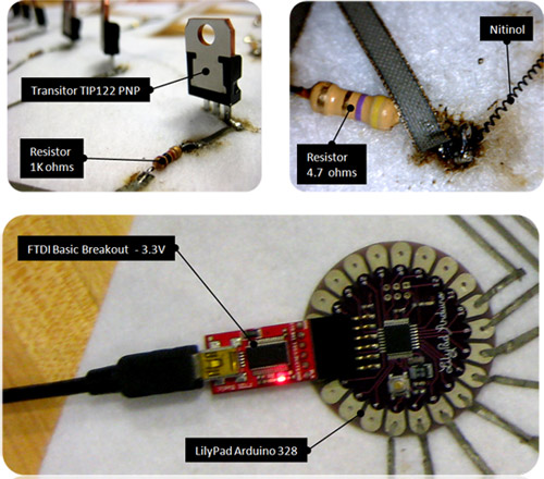
Components of the responsive fabric: transistors, resistors, nitinol wire, and a LilyPad Arduino.
I used Lilypad Arduino 328 as the main board to read the program, and attached the nitinol connection to its 6 pins. The Nitinol Biometal Helix (BMX15020, dia: 150 uM) originally contracted as a coil at 20 mm length and can be elongated until as twice as much of its original size (40-50mm) by attaching a 30 gram force. To pull the wire to move back to its contracted length, it needs to be activated by heating it with 70 C temperature or with a voltage of a 3 Volt battery. I used a 100 Ohm resistor to reduce the current from transistor to the LilyPad, and a 4.7 ohm resistor to reduce the current for the nitinol. Apparently, I didn’t need the second one since the current that fed the wire had too much resistance while it goes along the zelt. (In other words, if I can calculate the required length to reach a certain resistance, then I might not need a resistor at all, and that would make a seamless connection on the fabrics). As for the switch, I used transistor TIP122 PNP to read the arduino program of which flap should be activated. (Transistor base goes to the Lilypad, emitter goes to the negative, and collector attaches to the nitinol).
Scheme

Designing the responsive fabric layout with Google SketchUp.
In terms of design, I see the circuit board as analogous to the space programming process in architectural design. Accordingly, I created a blueprint of my circuit design using the simple Google SketchUp program for the following reasons:
- To anticipate the dimension of the components, such as the transistor or resistor size whether they are colliding or not, and the lilypad mainboard orientation so each pin would have enough space for its connection.
- To trace the positive and negative connection and see whether they are overlapping or not.
- To use the vector graphic image for further fabrication processes, for instance, cutting the shape on the rapid prototyping machine or stitching a pattern on the embroidery machine.
- To design and simulate the physical appearance of the project as a whole by rendering the material.
With this technique, we can get a sense of the scale of how the final product will look like just by printing the scheme on the paper. However, it is still not able to predict the performance of the design as a circuit board, since all connections need to be perfectly connected by whichever joint that we use.
Connection

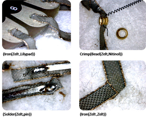
Four types of connections used in the responsive fabric.
As the most used technique in this scheme, ironing the zelt was very easy to do; however, I had to make sure that every joint was perfectly blended to each other. To attach the wire with the zelt, I used a metal bead and crimped the bead while the zelt and the wire were in its hole. Any other component with the pin, transistor and resistor, were soldered to the zelt. The only way to test whether they are perfectly assembled is to make sure that they are beeping continuously in the multimeter.
Procedure
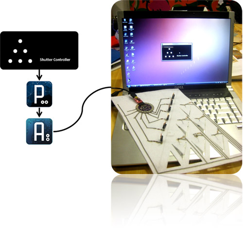
The goal of the procedure is to have the flaps move as the mouse position is over the dot on the shutter controller (see the screen). The procedure is the following: on the Shutter Controller, IF the mouse position is over the dot THEN the processing will send information (i) to the arduino. In the arduino, IF it’s receiving the information (i), THEN the arduino told the mainboard to turn on the PIN (HIGH). In the circuit, IF that PIN on the mainboard turns on, THEN the transistor will let the current feds the nitinol connected to that PIN so it will contract and pull the flap up.

Responsive fabric system diagram including laptop control.
Lessons learned
- Dealing with the resistance and nitinol behavior: To move the nitinol properly, I needed a specific value to let the correct current go through the wire. If there is too much resistance, it will move very slowly, or doesn’t move at all. If there is no resistance, it will burn the wire. So, I guess it would be nice to spend a good deal of time to get the best resistance value to heat the wire.
- Dealing with the nitinol cost: Due to the scheduling problems, I skipped the part where I should have shaped the nitinol myself (using a furnace with 500 C), and bought an expensive pre-shaped nitinol coil instead. Because of that, I can’t do much with this two 2 cm wire.
- Dealing with the connections: Most of my problems with the connection were caused by the lack of rigidity on the part where the component’s join together. So, I needed to make sure every joint is connected perfectly at each step, instead of completely connecting the whole circuit at the beginning and then testing it afterward.
- Finally, it is highly recommended to test the connection with a simple structure at each level: from arduino to the circuit and look at the connection by using multimeter (LED can tell us that there is a current goes by but doesn’t guarantee that there is enough power to move the nitinol); and from processing to arduino by checking that each the variable is sent as it should.
Many thanks to Leah for the guidance and troubleshooting the code and the circuit; and also to Marcelo for the idea of this project. This is certainly one of the best classes I ever took.
| « Previous: student work sample | Next: student work sample » |


