
« Laser Cutter Tutorial | Readings, Lectures & Tutorials Index | AVR Programming, Part 2 »
1. Make sure you’ve installed the necessary software.
Mac: CrossPack
Windows: WinAVR
Important Note for people running Windows: on Windows you will also have to install the driver for the USB programmer. If the driver does not successfully install automatically after you plug in the programmer, try downloading the latest libusb driver from SourceForge.
Unfortunately Windows 7 does not support the USB programmer we will be using, so if you have a machine with Windows 7 you should use the Mac computer in the high-low tech lab to do your programming.
For windows Vista 64, you need to first install AVR Studio 4. then install WinAVR 20100110. Then, download msys-1.0-vista64.zip (ZIP) and put that into your winavr/utils/bin directory. Then things should compile.
2. Get your materials together
ATtiny13 on a fabric PCB
AVRISP programmer with homemade alligator clip attachment
USB cable
3. Download some code
Download and unzip NewTextilesAVR.zip (ZIP) which contains all of the files you’ll need. Put the NewTextilesAVR folder on your desktop.
4. Open up a terminal window, a window that allows you to type out commands to send to your computer
On a Mac, go to the Applications→Utilities folder and open Terminal.app.
On a PC, go the Start menu and select Run. Then type cmd in the text box that pops up.
5. Navigate to the code folder within the NewTextilesAVR folder or “directory”
On a Mac, type the following command: cd Desktop/NewTextilesAVR/code
The cd stands for “change directory”.
6. Plug in your programmer and attach your circuit to your computer
Here is the pin layout diagram for the ATtiny13 chip – the miniature computer that we’ll be using. The diagram is from the ATtiny13 datasheet (PDF - 2.9MB).
ATiny13 pinout diagram. (© Atmel. All rights reserved. This content is excluded from our Creative Commons license. For more information, see http://ocw.mit.edu/fairuse)
The first important thing to know is how to orient the chip to the diagram. We need to know which way is up. If you look closely at the chip you will see a small dot in one corner. This dot indicates the top of the chip. When you match your chip to the diagram, the dot should be in the upper left hand corner of the chip, like so:
Orienting your ATiny13 device.
The diagram also shows the different functions of each leg of the ATtiny13 chip. To program the chip–to tell it what to do–we need to attach certain legs to our programmer.
Clip the programmer to your circuit, attaching the labeled alligator clips to the appropriate legs of the chip. Refer to the diagram above and follow the traces of your circuit. We need to attach + (also called “VCC” or “power” and usually colored red), - (also called “GND” or “ground” and usually colored black), RESET, MOSI, MISO, and SCK. Use the round piece of plexiglass to support your circuit. Here is a photograph that shows what the physical attachment should look like.
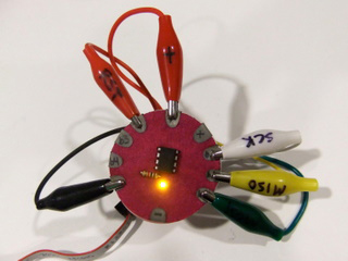
Attaching programmer to the ATiny13 using your circuit.
NOTE: IF YOUR CHIP IS GETTING HOT AFTER YOU ATTACH IT, UNPLUG EVERYTHING IMMEDIATELY. THIS MEANS YOU HAVE A SHORT & YOU’RE FRYING YOUR CHIP & MAYBE THE PROGRAMMER TOO.
7. Program your chip.
Type the following command in Terminal: make clean && make && make install
If all goes well, the LED on your fabric circuit should begin to blink.
8. Open the blink.c program file.
Browse to the NewTextilesAVR directory, open the code folder and double click the blink.c file to open it in a text editor.
Now we’re ready to start writing our own program… see AVR Programming Tutorial, Part 2: Writing Programs.
« Laser Cutter Tutorial | Readings, Lectures & Tutorials Index | AVR Programming, Part 2 »


