
« AVR Programming, Part 1 | Readings, Lectures & Tutorials Index
1. Open the blink.c program file.
Browse to the NewTextilesAVR directory, open the code folder and double click the blink.c file to open it in a text editor. For Windows, a simple and free editing program is Notepad++. Here’s what my file looks like in the TextEdit application:
The blink.c program file
This program is written in the C programming language.
The program is broken up in to a few different regions. Here are the ones we care about:
Functional regions of the blink.c program.
Comments Area
At the top of the page there is a comment section that gives some basic information about the program. This section is ignored by the computer. It’s just there to give us humans some information about the file. In general, a comment is a piece of text that is ignored by the computer. Comments can be anywhere in your program. There are two different ways to create comments:
\* Anything in between a slash and an asterisk and then
an asterisk and a slash, like this statement is a comment *\
OR
\\ A single line of text that follows two slashes like this line is also a comment.
Setup Area 1
This section is where we tell our program what other files it will need and set some basic parameters. We’ll be ignoring this section for now.
Setup Area 2
This section is where we tell our ATtiny13 which legs we’ll be using for which purpose. In our code the line b0Output() tells the ATtiny that an output (like an LED or a motor) will be attached to pin b0. Each pin on the ATtiny13 has a name like b0. To know which pin is which, you can refer to the pin diagram from the ATtiny’s datasheet. Here’s what that looks like:
ATiny13 pinout diagram. (© Atmel. All rights reserved. This content is excluded from our Creative Commons license. For more information, see http://ocw.mit.edu/fairuse)
Identify pin b0 on the diagram. Notice that in addition to b0 there are b1, b2, b3, b4, and b5. We can use b1-b4 in our programs. We will not be using b5 in any of our programs. We need to do a special kind of programming to use b5.
For every program that you create, you need to include a statement like b0Output() for every pin you would like to use to read information from a switch or to control an output device. Here’s what those statements look like:
b1Output(); this statement sets up pin b1 to control an output like a light or motor
b3Input(); this statement sets up pin b3 to read information from a switch
Main Action Area
This section is where the main action of our program takes place. In this piece of code we have 4 lines:
b0High(); this statement sets pin b0 to 5 volts. For our circuit this turns the LED attached to b0 ON.
_delay_ms(1000); this statement tells the ATtiny to do nothing for 1 second (1000 milliseconds)
b0Low(); this statement sets pin b0 to 0 volts or ground. For our circuit this turns the LED OFF.
_delay_ms(1000); this statement tells the ATtiny to do nothing for 1 second (1000 milliseconds)
Let’s look at the fabric PCB circuit to see why this piece of code would cause the LED on our board to light up. Here’s what the circuit looks like (view from above):
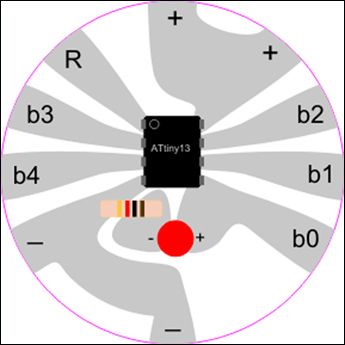
An example fabric PCB circuit.
Notice how the + side of the LED is attached to b0 and the - side of the LED is attached to ground through a resistor. When b0 is High, at +5V, current runs through the LED, causing it to turn on. When b0 is Low, at 0V, both sides of the LED are attached to ground, so no current flows and the LED turns off.
2. Understanding program structure.
The program is a list of instructions that tell the microcontroller (our ATtiny13) what to do. The ATtiny13 follows the instructions line by line, starting from the top and moving to the bottom. However, when it reaches the “for (;;)” statement, it does what is inside the curly brackets “{” and “}” after the for statement over and over again forever. When it reaches the closing curly bracket “}’” it jumps up to the opening curly bracket and begins again from the top:
Structure of the blink.c program.
3. Edit the code to get the LED to blink at a different speed.
To upload your edited code to your circuit, type the following command in Terminal: make && make install
4. Use alligator clips to attach a second LED to pin b3 and edit the code to get that LED to blink.
5. Use alligator clips to attach a switch to pin b1 and edit the code so that the LED attached to b0 comes on when the switch is pressed.
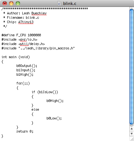
Example of edited blink.c program.
For the official AVR C programming language reference see the AVR libc documentation.
« AVR Programming, Part 1 | Readings, Lectures & Tutorials Index


